On 24/4/2018 at 11:15 PM, Edy said:
I don't think the wheel load alone is a good criteria. It's much more important the grip understood as the ability of the wheel to receive torque without slipping. We may simplify the grip as wheel load multiplied by the coefficient of friction of the tire.
Thanks so much for your help. I took a step back after your last reply and realized my mistake right here. Watching Youtube videos on Assetto Corsa and Project Cars differential setup helped a lot in understanding things visually and in terms of real world application.
Imagining an extreme situation helped me understand better, for example when one wheel is on tarmac and the other is on ice. The one on ice, let's say, has no grip at all, so it keeps on spinning. The other one on tarmac, receiving the same torque percentage, but that torque is not enough to overcome friction reaction torque (or the wheel is being held firmly) and roll the wheel, so the car is sitting duck. This is due to the spider gear setup that allows 2 wheels to spin independently. When one wheel is spinning while the other has traction, the spider gear would spin on its own axis, allowing the spinning wheel to keep on spinning and taking power from the traction wheel. That's why in road cars (even some super cars like the McLaren P1) with open diff, they would have a "poor-man" LSD where the brake of the spinning wheel is applied to transfer power to the dead wheel. The braking reduce the rotation of the spider gear and allow less independent rotation between two wheels
In LSD this is overcame by using clutch packs that connects the housing case to the axle. The housing in turns connected to the ring gear. In the clutch packs are steel plates connected to the case and friction disks connected to side gear (on the axle), so when they are pressed, the axle would rotate with the housing case and the ring gear. Because the spider gears are not connected directly to the housing, but rather through a pair of pressure rings )the rings are connected to the housing). When there is an acceleration from the engine to the ring gear, the case and the pressure rings, the spider gears are "lagged" behind and slid along the pressure rings, pushing the rings away, in turns pushing the clutch packs, creating locking force between axles. When there is no acceleration, the spider gear would sit quietly inside the pressure rings, rotate around their own axis and allow independent rotation between 2 axles
Found this on youtube, very helpful btw:
On 24/4/2018 at 11:15 PM, Edy said:
However, going for too much throttle does not cause the outer wheel to slip in an open differential (again, leaving inertial effects aside). All power is routed to the slipping wheel, leaving the adherent wheel producing the same -reduced- force as the slipping wheel.
The reason I had that idea is thinking of the engine torque being splitted 50-50 between 2 wheels in a constant function like this: leftTorque = rightTorque = engineTorque * 0.5f. So if the engine torque coming from the engine to the pinion gear increases, the amount of torque coming to both wheel would also increases, thus giving the dead wheel with traction more torque to work with and overcome traction reaction torque and rotate. But I realized it's much more complicated than that.
On 24/4/2018 at 11:15 PM, Edy said:
This means that if one wheel is in the air the LSD differential behaves exactly as an open differential: the adherent wheel receives no torque (only the torque caused by the inertial effects, to be exact).
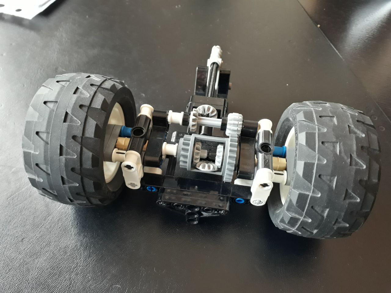
This is the only part where I still didn't get about LSD, but I think I do now. Say when one wheel is in the air, when there is acceleration coming in, the ring gear instead of "lagging" and pushing the pressure ring, would spin on their own axis and allow the wheel in the air to keep spinning and taking power from the dead wheel. The reason for the ring gears to not "lagging" is because of the very high traction reaction force from the dead wheel holding the wheel (and that axle) back, and the other wheel have no resistance at all, so when the spider gears rotate with the pressure rings, the gears don't receive any resistance from the spinning wheel to make them "lag" behind and push the pressure ring, thus making the spider gears spinning on their own axis, allowing for independent rotation of 2 wheels. This is actually better to understand using a modified LEGO diff with spider gears inside pressure rings, and hold one wheel while spinning the pressure ring. One would see that even though there is acceleration coming into the pressure ring, the resistance from the spider gears is not enough to push the pressuring away, and instead the power makes the spider gears rotate on their own axis
Is the above explanation correct?
On 24/4/2018 at 11:15 PM, Edy said:
However, locked and viscous differentials route the torque in a way so the torque produced by the engine is always transformed, entirely or as a fraction respectively, into tire forces among both wheels.
I realized this now. Locked diff is pretty obvious, engine torque is always going to both wheels since they move as a single unit. Viscous is basically a progressive locking diff based on velocity difference, so the locking force will progressively increase with speed difference until it is high enough to actually lockup the 2 axles.
On 24/4/2018 at 11:15 PM, Edy said:
A bias ratio of 2:1 means that while a wheel is slipping, the adherent wheel will receive twice as torque as the slipping wheel, thus allowing it to produce twice as force. This reduces the performance loss that would be produced in an open differential, as described above. A ratio of 4:1 means up to four times the force of the slipping wheel.
So an example of implementation: First I would calculate the difference in tire forces between wheels, and figure out clutch locking force by multiplying that difference with clutch locking friction strength. Then apply this amount of locking force (turn it to torque first) to the wheel with the less tire force opposite to the rolling direction of the wheel, which in other words, reducing the torque from the spinning wheel. This locking force/torque also apply to the adherent wheel same as the rolling direction of that wheel, or in other words, taking torque to the adherent wheel. For bias ratio, if the ratio of tire force between 2 wheels is less than or equal to the bias ratio, then use that difference in tire force to calculate locking force, otherwise, uh, where do I go from here? ")
Again thank you so so much. Having a conversation like this really clears things out for me. I got a hang of the mechanics behind the diffs now, what's left is actually come up with an implementation that suits the current drivetrain model I'm doing.
Oh by the way, I ditched Unity WheelCollider and wrote my own tire model, because having no way of extracting tire force is really frustrating. And really I don't know what the people doing PhysX is thinking, locking away a very important aspect like tire force.