Advertisement

Object vs ground constraint solver

Started by December 06, 2021 11:31 PM
10 comments, last by CasualKyle 3 years, 1 month ago

I'm trying to implement an impulse based constraint solver for the case of a 3D cube falling onto a horizontal plane. When a vertex of the box is below the plane, I'm solving the constraint where the vertex of the box should be anchored to the contact point on the plane i.e. a ball and socket joint.
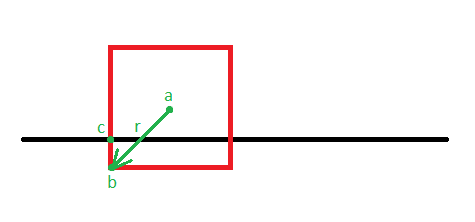
In this example I'm solving the constraint where b - c = 0. Since my constraint solver works at the velocity level, the idea here is that I'm applying an impulse to the cube at point b. This will both move the cube upwards and induce a rotation. Also, there is no restitution involved.

I'm trying to gain an intuitive understanding about whether my solver is working correctly or not. If I set the baumgarte stabilization coefficient to 1 such that the constraint is completely satisfied in one run of the solver then the cube should move & rotate such that b - c = 0 right? The problem I'm having is that this is not happening.
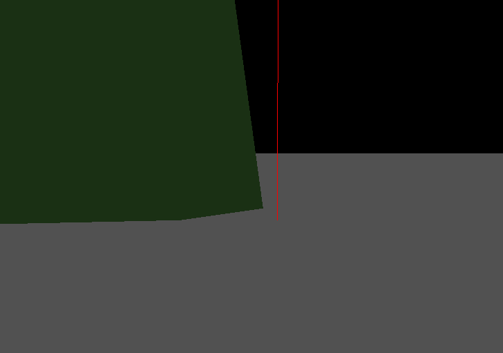
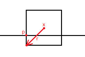
The point where the red line intersects the plane would be point c in the first diagram and the corner of the cube would be point b. This is the result of solving the constraint once with a baumgarte stabilization coefficient of 1, in that case is this correct? I don't think it is since b is not equal to c but I've checked the math and I cannot find a mistake. Because the math is so complicated, before I share any of the code which calculates the impulse is the assumption correct that these two points should be equal? Should the direction of the impulse be completely vertical? Or is it expected that it would have some non zero horizontal values to account for the rotation applied to the box?

Here is a breakdown of the code.

// integrate linear and angular velocity
box.velocity += ...;
box.angular_velocity += ...;

// integrate position and rotation
box.position += box.velocity * delta_time;

let w = Quaternion::new(box.angular_velocity.x, box.angular_velocity.y, box.angular_velocity.z, 0.0);
box.orientation += w * box.orientation * 0.5 * delta_time;
box.orientation.normalize();

if box vertex is below plane {
	// calculate force required to solve the constraint
	let f_linear = ...;
	let f_angular = ...;
	
	// integrate linear and angular velocity
	box.velocity += (1.0 / mass) * f_linear;
	box.angular_velocity += inertia_tensor_inverse * f_angular;
	
	// integrate position and rotation
	box.position += box.velocity * delta_time;
	
	let w = Quaternion::new(box.angular_velocity.x, box.angular_velocity.y, box.angular_velocity.z, 0.0);
	box.orientation += w * box.orientation * 0.5 * delta_time;
	box.orientation.normalize();
}

There are many possibilities to make a mistake, but note that if you have one-dimensional constraint (i.e. remove one DoF), you can only expect projected equation to be satisfied:

n * (b - c) = 0, where n is a contact normal.

Advertisement

@muleax Yes, but in my case the constraint is b - c = 0, there is no projection along a normal. So given my baumgarte stabilization coefficient is 1, when I apply the linear and angular constraint forces b - c should be 0 i.e. the point on the cube should equal the point on the ground right?

How did you make such a constraint? Did you use standard LCP formulation in cartesian coordinates ? It is effectively 3 different 1d-constraints?

It's a ball and socket constraint. I found it on page 12 of this paper and it's also explained at 25:00 in this video. There is only a position constraint since the box is free to rotate around the corner point. I'm not sure what you mean by 3 different 1d-constraints, it's a 3D position constraint. I guess the idea is you're subtracting the corner point on the box from the point on the ground which gives you a 3D vector. Then you constrain each of those 3 components to 0.

I see, so you are solving for Vector3 lambda (i.e. 3 lagrange multipliers). If you are solving the system just as in the video by inverting the system matrix, then Baumgarte with coefficient=1 should work just fine (for a few frames in the absence of other constraints). Of course, for longer simulation times or more complex systems BG coefficient should be lower, because inaccuracies will introduce energy to the system.

Advertisement

Right, yeah I'm not actually planning to have the Baumgarte stabilization coefficient be 1. I'm just using it as a way to determine whether the solver is working correctly or not. With a Baumgarte stabilization coefficient of 1, the constraint should be satisfied after a single timestep but that is not happening so I guess I can conclude I'm doing something wrong.

Consider setting BG coefficient to 0, and checking whether constraint on velocity is satisfied. I often find it helpful to debug this way.

So here is the problem I'm having…

I want to constrain point x + r on the cube to point p so we have the following position constraint.

Then we take the first derivative with respect to time to get the velocity constraint.

Where v is the linear velocity of the cube and omega is the angular velocity of the cube. So this equation gives the velocity of the point x + r.

Now we can use this to find J.

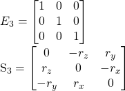
E3​ is a 3x3 identity matrix and S3​ is a 3x3 skew matrix:

I've confirmed this skew matrix works:

Now I'll write down everything we know including m, the mass of the cube, I, the 3x3 inertia tensor of the cube and b, the term which corrects for positional drift where beta is the Baumgarte stabilization coefficient.

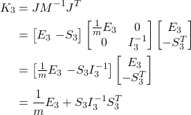
With this information we can solve for lambda starting with the 3x3 matrix K.

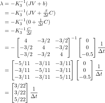
Now we can find lambda which is a column vector of 3 elements.

Then the impulse is:

Which we can split up into the linear and angular components.

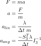
Using this we can solve for the force.

Then solve for acceleration.

Finally, now we can find the velocity.

I don't think there is any mistake here, this is what you find in the ball and socket section on page 12 of this paper and at 25:00 in this video.

Now I'm going to run through an example which will show the issue I'm having.

I'll give these points actual numbers and run through the solver manually. If I use a Baumgarte stabilization coefficient of 1, all the positional drift should be gone in a single timestep, i.e. point x + r should equal point p. So let's go through this horrible pain and see if it works.

The center point, or point x of this 2x2x2 3D cube is positioned at (0, 0, 0.5). In this coordinate space z is the vertical axis and of course vectors are expressed as (x, y, z). The direction vector r is (-1, -1, -1) so that the cube's corner point x + r is (-1, -1, -0.5). Point p is positioned at (-1, -1, 0). Point x + r is directly below point p by 0.5. Let's stick with simple numbers and let the mass of the cube m, be 1.

Now we can solve lambda which starts with finding the matrix S.

And the matrix I, the side length of the cube is 2 and the mass is 1.

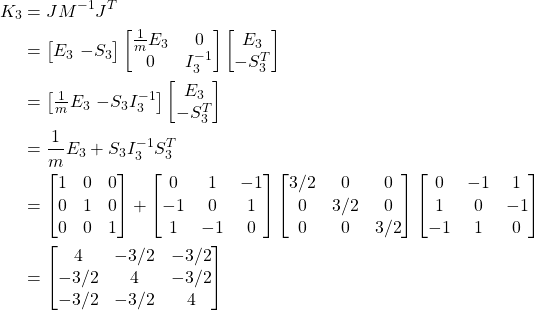
Now we can find the matrix K.

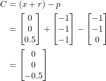
We also need to find the value of C, the position constrain function which is the difference between point x + r and p.

Next we can solve for lambda. To keep the example as simple as possible, let's make the current linear and angular velocity of the cube 0. Also, as discussed the Baumgarte stabilization coefficient will be 1.

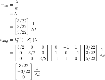
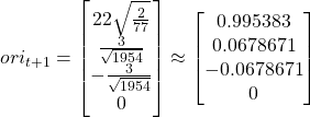
Now we can find the linear and angular velocity.

EDIT: I calculated -S^T wrong here, the angular velocity should be (-3/22, 3/22, 0)(1/dt).

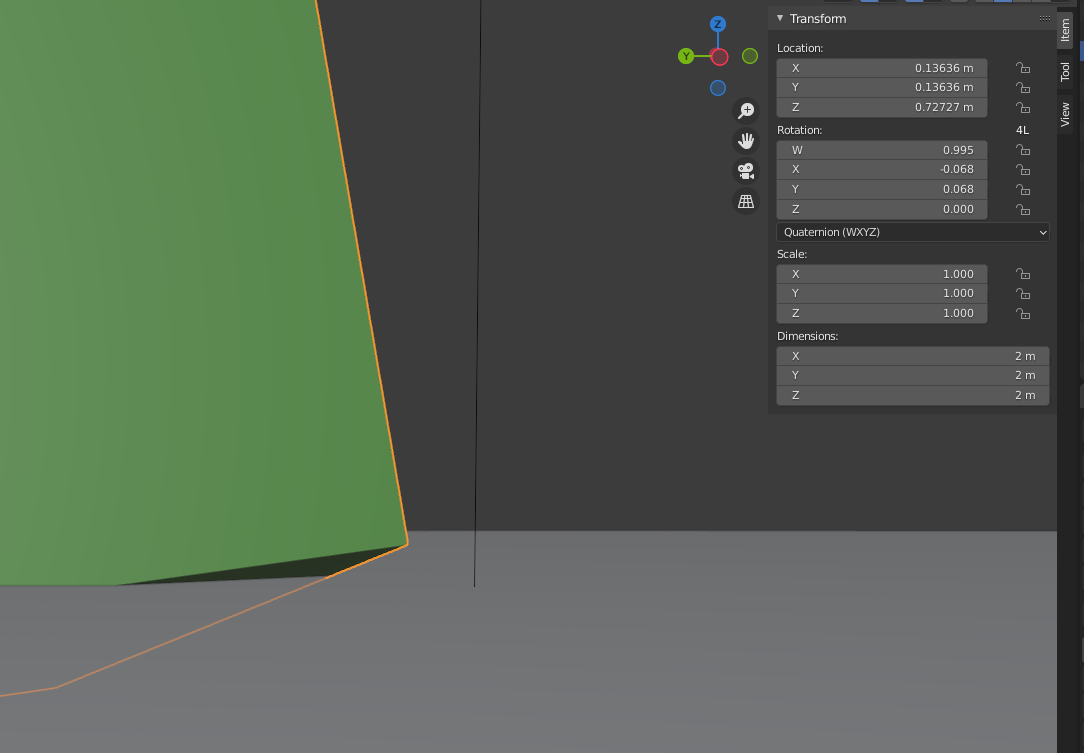
Finally we can update the position and orientation of the cube with these new velocities to check if it worked. Here is the new position of the cube.

When finding the new orientation, we have to define a quaternion w which is of the form (w, x, y, z). The x, y and z components are that of the angular velocity and w is set to 0.

The last step is to normalize the quaternion.

Now let's see if this new position and orientation worked.

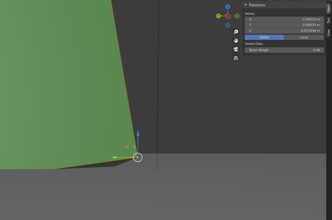
It didn't, here is the position of that corner at (-0.98033, -0.98033, 0.015936). It should be at (-1, -1, 0).

After typing all this up and thinking about what could be the culprit of error, I starting thinking about the integration techniques used in this math. I think what I'm seeing here is probably a result of using numerical integration since that will only compute an approximate solution. I'm solving for an impulse, then doing a numerical integration to get the force, then another numerical integration to get the acceleration, another numerical integration to get the velocity and one more to get the displacement. That's a lot of integrations so I bet that explains the error.

For my actual simulation, I'm not going have a Baumgarte stabilization coefficient of 1 so this positional drift will get resolved over the course of many frames. As the point gets closer to where it should be, the error becomes less and less noticeable. So the error is proportional to the distance between the two points. All this is to say the error will not be noticeable in my actual simulation.

So unless someone can find some issue with what I've done, I'm going to chalk this error up to numerical/semi implicit euler integration and move on.

I think the "issue" here is that BG stabilization works with linear approximation of the trajectory. The solver is designed to work with semi-implicit integrator and to satisfy constraints on velocity. If we have a ball-socket joint with static ground, then without stabilization solver will find such lambda that leads to the contact point velocity change such that:

V1 + dV = 0, where V1 is velocity at the beginning of the frame

BG stabilization effectively modifies dV such that:

V1 + dV' = pos_error / dt

BG stablization only take into account local linear approximation of the movement. So, imagine observing the body at time t1 just after impulses being applied. Contact point is now moving with velocity V2 = pos_error / dt. If it continue to move with this velocity, then at time t2 position error should be eliminated. But V2 is just an instantaneous velocity at t1, and it's only a good approximation in a small local area. Body also receives angular velocity, so contact point velocity will change during dt.

This effect should be less noticeable when term r x w is small: smaller penetrations (usual case) or, for example, if you rotate the box on 45 degrees and collide with horizontal ground.

This topic is closed to new replies.

Advertisement