Advertisement

Cel shading edge detect.

Started by January 11, 2018 05:39 PM
7 comments, last by JoeJ 7 years ago

https://en.wikipedia.org/wiki/Cel_shading in this Wiki it mentions:  "A Sobel filter or similar edge-detection filter is applied to the normal/depth textures to generate an edge texture. Texels on detected edges are black, while all other texels are white:"

How would I do this with Unity?

I know about the reverse mesh trick but because of strict polygon limits it is no longer a option. I have been looking for a Sobel filter shader for Unity to learn from but all I found was a very old one, that doesn't work.

I see you've tagged mobile but did you consider [ this ] from the standard assets package?

Dev careful. Pixel on board.

Advertisement
3 hours ago, GoliathForge said:

I see you've tagged mobile but did you consider [ this ] from the standard assets package?

Thanks, but I can't use anything from the Unity asset store.

The composing would have to be adjusted to work with the special way that our scene is lighted. This means either altering or reverse engineering the shader. Both these things are forbidden by the Unity asset store licence; you are only allowed small tweaks. 

As this is for a commercial game we can't have any legal problems and as a result can't use one of the shaders or effects from the Unity asset store. Also can't afford to hire a pro.

I have found some sobel descriptions and have started to work this out. At the moment I get only the outside outline, it's not reading my normal map, depth or contours.


Basically I need to learn how to do this from scratch. It isn't that I can't do it but it will take me some time so any advice on this will help me.

It also has to be optimized for mobile, that I have no idea how to do.

If you use mirror-ball image based lighting you talked about recently, you could experiment with drawing a black circle around the ball :) (Or achieve the same effect by darkening if per pixel normal is tangent to view direction within some soft threshold - less false positives and faster than edge detection by post process, but probably very bad for flat geometry at shallow angles.)

Edit: to fix the problem of large dark areas on flat geometry e.g. a cube, you could use a precalculated texture the is black where you allow the darkening to happen, and white otherwise. So for the cube only the edges would be black and for a sphere the entire texture would be black. Finally you would have good control of the stroke width. Baking of this texture should be driven by mesh curvature.


20 minutes ago, JoeJ said:

If you use mirror-ball image based lighting you talked about recently

With my matcap experiments I know that this won't work exactly. Matcaps takes the camera angle so sometimes the outline will be thin around the edge and other times it would cover the whole model when you look from a angle. Matcaps mostly work from fixed viewpoints.


I am making progress, I learned how to get the normal and depth pass from Unity and have a outline. I just need to learn how to use the normal map to also apply lines on the mesh.

1 hour ago, Scouting Ninja said:

Matcaps takes the camera angle so sometimes the outline will be thin around the edge and other times it would cover the whole model when you look from a angle.

Yep, that's why i thought about curvature maps to get control. I quickly tried it out - seems an interesting idea maybe nobody implemented yet. I did it only per face, here are some images.

As expected i get rid of 'whole side view black' (the side of the cube would be black without the curvature map).

But the stroke i get is too thin in comparison to the sphere :( and there is of course no stroke on the front of the cube :( and avoiding too sharp edges also does not help enough :(

Maybe with more work it becomes acceptable, but no break-through. Can't help with edge detection method either.


cel.JPG

round.JPG

curv.JPG

Advertisement
6 minutes ago, JoeJ said:

I quickly tried it out

Looks very interesting. Will keep it in mind, never know when something like this could be handy.


I am having problems with Unity screen effects on mobile so I think I should just abandon this idea and re-work my meshes so I can use the flipped mesh effect. It will take hours but this has taken me two days with very little progress.

Some times I feel like Unity just hates me and the feeling is mutual.

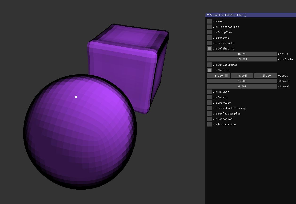
... got the idea to blur normals, so flat / round stuff isn't that different.

Also previously i used manual setting for eye position which made sphere stroke even wider.

Looks much better now, also no popping under camera movement. But the need for second normal channel hurts, or you'd accept that smooth look for everything :)

Edit: The blurred normals do all the trick now. curvature map might not be necessary anymore.


static bool visCelShading = 0; ImGui::Checkbox("visCelShading", &visCelShading);
		if (visCelShading)
		{
			static float radius = 0.19f;
			ImGui::DragFloat("radius", &radius, 0.01f);

			static std::vector<vec> vertexCurvatureDirectionsBoth;
			static std::vector<float> vertexConeAngles;

			if (ImGui::Button("Update Curvature") || vertexConeAngles.size()==0)
			{	
				mesh.BuildVertexCurvatureDirections (
						&vertexCurvatureDirectionsBoth, 0, 0,
						&vertexConeAngles, 0, 0, 
						0, radius, mesh.mVertexNormals, mesh.mPolyNormals);
			}

			static float curvScale = 15.0f;
			ImGui::DragFloat("curvScale", &curvScale, 0.01f);

			std::vector<float> vertexMap;
			vertexMap.resize(mesh.mVertices.size());
			for (int i=0; i<mesh.mVertices.size(); i++)
			{
				//vertexMap[i] = vertexCurvatureDirectionsBoth[i].Length() * curvScale;
				vertexMap[i] = fabs(vertexConeAngles[i]) * curvScale;
			}

			std::vector<float> blurredVertexMap;
			mesh.BlurVertexMap (blurredVertexMap, vertexMap);
			std::vector<float> polyCurvatureMap;
			mesh.VertexMapToPolyMap (polyCurvatureMap, vertexMap);

			static int blurIter = 10;
			ImGui::DragInt("blurIter", &blurIter, 0.01f);

			std::vector<vec> blurredVertexNormals1 = mesh.mVertexNormals;
			std::vector<vec> blurredVertexNormals2;
			for (int i=0; i<blurIter; i++)
			{
				mesh.BlurVertexMap (blurredVertexNormals2, blurredVertexNormals1);
				mesh.BlurVertexMap (blurredVertexNormals1, blurredVertexNormals2);
			}

			std::vector<vec> smoothPolyNormals;
			mesh.VertexMapToPolyMap (smoothPolyNormals, blurredVertexNormals1);
			for (int i=0; i<smoothPolyNormals.size(); i++) smoothPolyNormals[i].Normalize();


			static bool visCurvatureMap = 0; ImGui::Checkbox("visCurvatureMap", &visCurvatureMap);
			if (visCurvatureMap)
			{
				for (int i=0; i<mesh.mPolys.size(); i++) 
				{
					float c = polyCurvatureMap[i];
					float col[3] = {c,c,c}; VisPolyFilled (mesh, i, col);
				}
			}
			
			static bool visShading = 1; ImGui::Checkbox("visShading", &visShading);
			if (visShading)
			{
				vec lightPos (4,5,-3);
				//static vec eyePos (8,4,-2);
				//ImGui::SliderFloat3 ("eyePos", (float*)&eyePos, -10,10);
			
				static float strokeT = 0.2f;
				ImGui::DragFloat("strokeT", &strokeT, 0.01f);

				static float strokeS = 2.0f;
				ImGui::DragFloat("strokeS", &strokeS, 0.01f);

				RenderPoint (eyePos, 1,1,1);

				for (int i=0; i<mesh.mPolys.size(); i++) 
				{
					vec pos = mesh.mPolyCenters[i];
					//vec normal = mesh.mPolyNormals[i];
					vec normal = smoothPolyNormals[i];
					vec LightD = vec(pos - lightPos).Unit();
					float NdotL = max (0, normal.Dot(LightD));
					float ambient = 0.4f;
					float rec = NdotL + ambient;

					float strokefactor = max (0, min (1, polyCurvatureMap[i] ));
					vec eyeD = vec(pos - eyePos).Unit();
					float NdotE = max (0, normal.Dot(eyeD));
					NdotE = (NdotE*0.98f + NdotL + 0.02f); // wider stroke in shadow
					float tangF = 1.0f - sqrt(NdotE);
					float darken = max (0, min (1, tangF*strokeS - strokeT)) * strokefactor;

					vec diff (0.5f, 0.2f, 0.7f);
					diff *= (1.0f-darken);
					vec lit = diff * rec;

					VisPolyFilled (mesh, i, &lit[0]);
				}
			}
		}


smoothed.JPG

This topic is closed to new replies.

Advertisement