
May 26 2018
3dBook Update
Nearly six months have passed since updating this blog; a time spent getting the
3dBook-Reader code ready for github.
https://github.com/3dBookguy/Proj3dBook
I'm not sure how well I succeeded. I can say: The code is there and it is much cleaner
than it was at the end of last year. It builds and runs in my environment, which is
VS 2017 on Windows 10. It also builds and runs on my older laptop VS 2012 on Windows 8.
I hope it will do the same for anyone cloning it. See doc\ building.txt.
Along with the source code( Win32 C++ ), there are some "books" for it to read.
What good is a reader without something to read? Why the quotes around books?
Well, the longest title "Rendering the Platonic Solids" is some 30 pages, and the
rest are just a few pages. So maybe short essays or some such. However if a picture
is worth a thousand words, then perhaps a three dimensional rendering is worth ten thousand. And a thirty page offering is not such a trifle.
These 3dBook-Reader "books" are Unicode files with the .tdr extension. They are
lightly formatted so the 3dBook-Reader can respond to the text, and links in the text,
to interact with the reader.
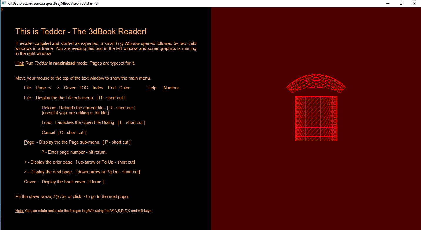
What the heck is the 3dBook-Reader anyway? Good question! A Windows program with a
"text" window and an Open GL window. So you can have a book with full 3d graphics.
You really need to build it and use it to know. Ex: You could have the text to a game
in one window and the game running in the other.
Why the quotes around text? This "text" window is really the directWrite - direct2D
window. So it has all the features of those two powerful API's. One a typesetting
engine and one a 2D graphics API.
So developing the 3dBook-Reader means developing the books it reads and graphics it
presents along with it. And yes: It is as much fun as it sounds! You may feel like
Magister Ludi Joseph Knecht in Hermann Hesse's "The Glass Bead Game".
"Rendering the Platonic Solids" doesn't just write about and present code for rendering
the solids: It actually renders them in the graphics window step by step - interacting with the text and reader.
Interaction:That really is the development emphasis and challenge.
As promised:
The octahedron and dodecahedron Platonic solids have been added to complete the library
on the five Platonic solids. If you can get the 3dBook-Reader source to compile and run;
all the Platonic solids are rendered, step by step, in "Rendering the Platonic Solids".
This file is in \doc\platonic.tdr. Or you can just read the file itself; it's a Unicode
file, formatted for the 3dBook-Reader, but readable by a human.
_____________________________________________________________________________
8 - 2018
Original Post
After a break of several years the 3D book project is back on. A few short words now on what this blog is about. I have to deliver my wife to the bus station in a few minutes, then a week alone so may have the time then to explain things. But the 3D book is something I started in 014 and put several years into, then the break, now on again. A win32 app with a text window and an ogl window.
I just remembered I had something written on this so here it is
I write to see if anyone in this community of game developers, programmers, enthusiasts, may be interested in a project I have been developing[off and on] for several years now.
So follows a short description of this project, which I call the 3D-Book project.
The 3D-Format Reader: A new format of media. Imagine opening a book, the left page is conventional formatted text - on the right page a 3D animation of the subject of the text on the left hand page. The text page with user input from mouse and keyboard, the 3D page with user input from a game pad.
An anatomy text for a future surgeon, with the a beating heart in 3D animation.
A children's story adventure book with a 3D fantasy world to enter on the right page.
...
Currently 3D-Format Reader consists of a C++ Windows program: Two "child" windows in a main window frame. Two windows: a text-2D rendering window and a 3D-rendering window. The text-2D window, as its' name implies, displays text and 2D graphics; it is programmed using Microsoft's DirectWrite text formatting API and Microsoft's Direct2D API for 2D graphics. The 3D-rendering window uses the OpenGL API.
A 3DE-Book page is formatted in one of two possible modes: DW_MODE or GL_MODE. In GL_MODE both windows are shown; the text-2D rendering window is on the left and the 3D OpenGL window is on the right. In DW_MODE, only the text-2D rendering window is shown, the OpenGL window is hidden (Logically it is still there, it has just been given zero width).
The 3D-Format Reader reads text files, which consists of the text of the book, control character for the formatting of text, (bold, underline, ...), display of tables, loading of images(.jpg .png ...), and control of 2D and 3D routines.
3D-Reader programming is based on a Model-View-Controller (MVC) architecture. The MVC design is modular: The Controller component handles user input from the operating system , the Model component processes the input, and the View component sends output back to the user on the display. Typical Parent-Child windows programs have multiple "call back" window procedures(winProcs): One for the parent window and one for child window. The MVC model, simplifies message routing by using a call-back window procedure which receives Windows messages for the main window, the text-2D window and the OGL window.
A sample MVC program by Song Ho Ahn was used as a template for the 3DE-Reader.
Rushed for time now, so a hasty sign off and thanks for reading.
----------------------------------------------------------------------------------------------------------------------------------------------------------------------------------------------------------------------------------
8 - 21 -18
I spent the last few days working on procedural mesh generation. First looking to find a bit of code to do what I had in mind. Which begs the question: What
did I have in mind? I just wanted a cube mesh generator such that...
Requirements
Input: An integer n = units from origin to cube face.
Output:
- The vertices for a unit cube centered on the origin.
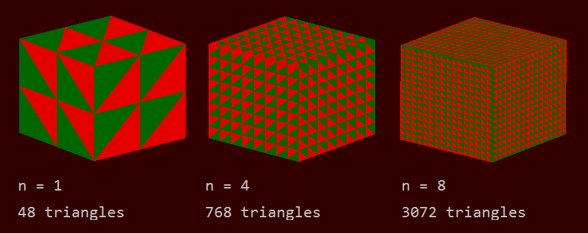
- 8n² triangles per cube face.
- 3 times 8n² verts in clockwise winding order (from the outside of the cube) ready for the rendering pipeline.
Screenshot of some cubes generated with the procedural cube mesh generator.
That was about it for the output requirements. I did not want to hand code even a single vertex and did not want to load a mesh file. I was sure the
code was out there somewhere, but was not finding it. So, a bit reluctantly at first, I started coding the mesh generator. I started enjoying creating this thing and stopped searching for the "out-there-somewhere" code; although still curious how others did this.
Analysis
First question: How do we number the verts? It would be great to conceive of some concise algorithm to put out the cube face verts all in clockwise
order for the outside faces of the cube directly. That seemed beyond me so I plodded along step by step.
I decided to just use a simple nested loop to generate the cube face verts and number them in the order they were produced. The hope(and the presumption) was: The loop code was in some order, running thru the x y and z coordinates in order, from -n to +n, therefore the output would be a recognizable pattern.
The simple nested loop vert generator did not let us down: It gave us a recognizable pattern, at least for this face. It turned out (as expected now) that all six faces have similar recognizable patterns. Plotting the first row or two of verts you can easily see how to run the rest of the pattern.
Plot of the first(of six) cube faces verts output by the vert generator: Input of n: There are (2n+1)² verts per cube face, or 25 verts for n = 2.
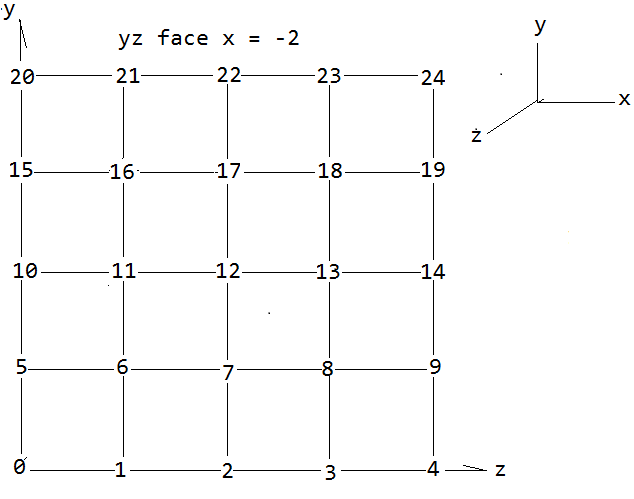
This is looking at the x = -n face from the outside of the cube. To simplify the math it helps to define s = 2n. Then there are
(s + 1)² verts, or 25 for s = 4
s² cells on the face, or 16 for 4 = 2.
We are going divide each cell into 2 triangles, so there are 2s² triangles per face, or 32 for s = 4.
Second question: What pattern for the triangles? How to number the 2s² = 32 triangles? What we want in the end is a bit of code such that... for triangles T[0] thru T[2s²-1] or T[0] thru T[31]( for n = 4), we have T[N] = f0(N), f1(N), f2(N). Where f0(N) gives the first vertex of T[N] as a function of N. and f1 and f2 give the second and third verts, all in CW winding order looking into the cube of course.
Here the choice is a bit arbitrary, but it would seem to make things easier if we can manage to have the order of triangles follow the order of verts to a degree.
Numbering the triangles.
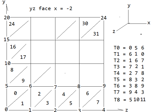
And now the problem becomes: Look at the triangle vert list, T0 - T8...T31 in the image, and try to discern some pattern leading us to the sought after functions f0(N), f1(N), f2(N) where N is the number of the triangle, 0 thru 2s²-1. This really is the holy grail of this whole effort; then we have T[N] = f0(N), f1(N), f2(N) and that list of verts can be sent directly to the rendering pipeline. Of course we want these functions to work for all six faces and all 12s² triangles to cover the cube. But first let's see if we can just do this one face, 0 thru 2s²-1..
Thru a bit of trial and error the 32 triangles(T0 - T31) were ordered as shown.
Now we have an ordered list of the triangles and the
verts from our loop.
T0 = 0 5 6
T1 = 6 1 0
T2 = 1 6 7
T3 = 7 2 1
T4 = 2 7 8
T5 = 8 3 2
T6 = 3 8 9
T7 = 9 4 3
T8 = 5 10 11 ... T30 T31.
If we can find a pattern in the verts on the right side
of this list; we can implement it in an algorithm and
the rest is just coding.
Pattern recognition:
It appears
T2 = T0 with 1 added to each component
T3 = T1 with 1 added to each component
In general T[N+2] = T[N] with 1 added to each component, until we come to T8 at least. Also it is hard to recognize a relation between the even and odd triangles,To see what is happening here it helps to look at an image of the generalized case where n can take on any integer value n > 0.
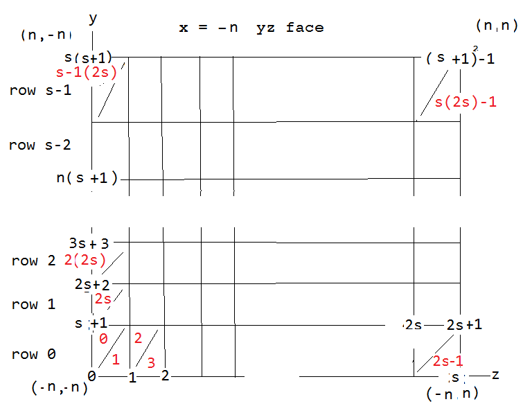
Looking for patterns in this generalized(for any n) vert plot we see...
We have defined s = 2n.
The 4 corner coordinates(+-n,+-n) of the x = - n cube face, one at each corner (+-n,+-n).
There are (s+1)² verts/face numbered (0 thru (s+1)² -1).
There are 2s² triangles/face numbered (0 thru 2s² -1). They are indicated in red.
It's not as bad as it looks iff you break it down. Let's look at the even triangles only and just the 0th vert of these triangles. For any row we see the number of that first vert of the even triangles just increases by one going down the row. We can even try a relation such as T[N].0 = N/2. Here T[N].0 denotes the 0th vert of th Nth triangle. Which works until we have to jump to the next row. Every time we jump a row we T[N+1].0 = T[N].0 + 2 for the first triangle in the higher row. So we need a corrective term to the T[N].0 = N/2 relation that adds 1 every time we jump a row. We can use computer integer division to generate such a term and N/2s is such a term. It only changes value when we jump rows and we get our first function ...
f0(N) = N/2 + N/2s. (even triangles)
Remember the integer division will discard any remainder from the terms and check this works for the entire cube face, but only for the even triangles. What about the odd triangles? Going back to the triangle vs vert list for the specific case n = 2, s = 4 for the first row; we see for the odd triangles T[N].0 = T[N-1].0 + s + 2. And adding this term, s + 2 to the formula for the even triangle 0th vert we get f0[N] for the odd triangles.
f0(N) = N/2 + N/2s + s + 2. (odd triangles)
Continuing this somewhat tedious analysis for the remaining functions f1(N), f2(N) we eventually have these relations for the x = -n cube face triangles.
for N = 0 thru N = 2s² - 1.
defining m = N/2 + N/2s.
T[N] = m, m + s + 1, m + s + 2 T[N] = f0(N), f1(N), f2(N). (even N)
T[N] = m + s + 2, m + 1, m T[N] = f0'(N), f1'(N), f2'(N) (odd N)
So it turns out we have two sets of functions for the verts, fn(N) for the even triangles and fn'(N) for the odd.
To recap here; we now have formulae for all the T[N] verts as functions of N and the input parameter n:
Input: An integer n = units from origin to cube face.
But this is only for the first face x = -n, we have five more faces to determine. So the question is: Do these formulae work for the other faces? And the answer is no they do not, but going through a similar analysis for the remaining face gives similar T[N] = f0(N), f1(N), f2(N) for them. There is still the choice of how to number the remaining triangles and verts on the remaining five faces, and the f0(N), f1(N), f2(N) will depend on the somewhat arbitrary choice of how we do the numbering. For the particular choice of a numbering scheme I ended up making, it became clear how to determine the f0(N), f1(N), f2(N) for the remaining faces. It required making generalized vert plots for the remaining five face similar to the previous image. Then these relation emerged...
For face x = -n T[N] N(0 thru 2²-1) we have the f0(N), f1(N), f2(N), even and odd
For face x = n T[N] N(2s² thru 4s²-1) add (s+1)² to the x=-n face components and reverse the winding order
For face y = -n T[N] N(4s² thru 6s²-1) add 2(s+1)² to the x=-n face components and reverse the winding order
For face y = n T[N] N(6s² thru 8s²-1) add 3(s+1)² to the x=-n face components
For face z = -n T[N] N(8s²0 thru 10s²-1) add 4(s+1)² to the x=-n face components
For face z = n T[N] N(10s²0 thru 12s²-1) add 5(s+1)² to the x=-n face components and reverse the winding order
And these are enough to allow us to write explicit expressions for all 12n² triangles for all 6 faces T[N] and what remains to be done is to implement these expression in code. Which turned out to be a much simpler task than finding the f0(N), f1(N), f2(N) and resulted in a surprisingly short bit of code.
Implementation
I have attempted to make this C++ snippet of code as generic as possible and have removed any dev-platform specific #includes and the like. GLM, a C++ mathematics library for graphics developed by Christophe Riccio is used. It is a header only library.
https://github.com/g-truc/glm/releases/download/0.9.9.0/glm-0.9.9.0.zip
That is the only outside dependency.
//  Procedural cube face verticies generator

#include <vector>
#include <glm/gtc/matrix_transform.hpp>


struct Triangle
{
    glm::vec3 vert[3]; // the three verts of the triangle
};

/*

std::vector<Triangle> cube_Faces(int n)

Input:        integer 'n'; the units from origin to cube face.

Output:        vector<Triangle> glTriangle; container for the
            12*(2*n)² triangles covering the 6 cube faces.

*/

std::vector<Triangle> cube_Faces(int n){

    size_t number_of_triangles(12*(2*n )*(2*n));
    size_t number_of_face_verts(6*(2*n +1 )*(2*n+1));
    std::vector<glm::vec3> face_verts(number_of_face_verts);
    std::vector<Triangle> glTriangle(number_of_triangles);

//  Generate the 6*(2n +1 )² face verts -------------------------------

    int l(0);
    for(int i = 0; i < 6; i++){
        for(int j = -n; j <= n; j++){
            for(int k = -n; k <= n; k++){
                // Below "ifS" strip out all interior cube verts.
                if( i == 0){ // do yz faces
                    face_verts[l].x = (float)(-n); //x
                    face_verts[l].y = (float)j; //y
                    face_verts[l].z = (float)k;}//z
                if( i == 1){ // do yz faces
                    face_verts[l].x = (float)(n); //x
                    face_verts[l].y = (float)j; //y
                    face_verts[l].z = (float)k;}//z
                if( i == 2){ // do zx faces
                    face_verts[l].x = (float)j; //x
                    face_verts[l].y = (float)(-n); //y
                    face_verts[l].z = (float)k;}//z
                if( i == 3){ // do zx faces
                    face_verts[l].x = (float)j; //x
                    face_verts[l].y = (float)(n); //y
                    face_verts[l].z = (float)k;}//z
                if( i == 4){ // do xy faces
                    face_verts[l].x = (float)j; //x
                    face_verts[l].y = (float)k; //y
                    face_verts[l].z = (float)(-n);}//z
                if( i == 5){ // do xy faces
                    face_verts[l].x = (float)j; //x
                    face_verts[l].y = (float)k; //y
                    face_verts[l].z = (float)(n);}//z
                l++;
            }
        }
    }

//  Generate the 12*(2*n)² triangles from the face verts -------

    int s = 2*n;    int q = 2*s*s;    int a = (s+1)*(s+1);
    int f(0);        int r(0);        int h(0);

    for( int N=0; N < number_of_triangles; ){
        // triangles already in CW winding
        if( N <  q || N <  5*q && N > 3*q - 1  ){
            // do the even indicies
            f= q*(N/q); r = a*(N/q); h = (N-f)/2 + (N-f)/(2*s) + r;
            glTriangle[N].vert[0] = face_verts[h];
            glTriangle[N].vert[1] = face_verts[s + 1 + h];
            glTriangle[N].vert[2] = face_verts[s + 2 + h];
            N++; f= q*(N/q); r = a*(N/q); h = (N-f)/2 + (N-f)/(2*s) + r;
            // do the odd indicies
            glTriangle[N].vert[0] = face_verts[s + 2 + h];
            glTriangle[N].vert[1] = face_verts[ 1 + h];
            glTriangle[N].vert[2] = face_verts[h];
            N++; f= q*(N/q); r = a*(N/q); h = (N-f)/2 + (N-f)/(2*s) + r;
        }
        // triangles needing reverse order for CW winding
        if( N >  5*q - 1 || N <  3*q && N > q - 1 ){
            // do the even indicies
            glTriangle[N].vert[0] = face_verts[s + 2 + h];
            glTriangle[N].vert[1] = face_verts[s + 1 + h];
            glTriangle[N].vert[2] =  face_verts[h];
            N++; f= q*(N/q); r = a*(N/q); h = (N-f)/2 + (N-f)/(2*s) + r;
            // do the odd indicies
            glTriangle[N].vert[0] = face_verts[h];
            glTriangle[N].vert[1] = face_verts[1 + h];
            glTriangle[N].vert[2] = face_verts[s + 2 + h];
            N++; f= q*(N/q); r = a*(N/q); h = (N-f)/2 + (N-f)/(2*s) + r;
        }
    }

//  Normalize the cube to side = 1 ------------------------------

    for(int i = 0; i < number_of_triangles; i++){
        glTriangle[i].vert[0].x = glTriangle[i].vert[0].x/(2.0*(float)n);
        glTriangle[i].vert[0].y = glTriangle[i].vert[0].y/(2.0*(float)n);
        glTriangle[i].vert[0].z = glTriangle[i].vert[0].z/(2.0*(float)n);
        glTriangle[i].vert[1].x = glTriangle[i].vert[1].x/(2.0*(float)n);
        glTriangle[i].vert[1].y = glTriangle[i].vert[1].y/(2.0*(float)n);
        glTriangle[i].vert[1].z = glTriangle[i].vert[1].z/(2.0*(float)n);
        glTriangle[i].vert[2].x = glTriangle[i].vert[2].x/(2.0*(float)n);
        glTriangle[i].vert[2].y = glTriangle[i].vert[2].y/(2.0*(float)n);
        glTriangle[i].vert[2].z = glTriangle[i].vert[2].z/(2.0*(float)n);
    };

    return glTriangle;
}
The rendering was done using OpenGl.
//  OGL render call to the cube mesh generator - PSUEDOCODE

int n(2);
int cube_triangle_Count = (12*(2*n)*(2*n));
std::vector<Triangle> cube_Triangles(cube_triangle_Count);
cube_Triangles = cube_Faces(n);
glBindBuffer(GL_ARRAY_BUFFER, uiVBO[0]);
glBufferData(GL_ARRAY_BUFFER, cube_Triangles.size()*sizeof(Triangle), &cube_Triangles[0], GL_STATIC_DRAW);
glVertexAttribPointer(0, 3, GL_FLOAT, GL_FALSE, 3*sizeof(float), 0);
glEnableVertexAttribArray(0);
glDrawArray(GL_TRIANGLES,0,3*cube_triangle_Count);
This just gets the position attribute of the cube face triangle verts; for the color and other attributes there are a couple of options: Use separate GL_ARRAY_BUFFERS for the color and other attributes. Or add attributes to the Triangle struct...
struct Triangle
{
	glm::vec3 vert[3]; // the three verts of the triangle
	attribute1;
	attribute2;
	...
};
Screenshot of the spherified cube.
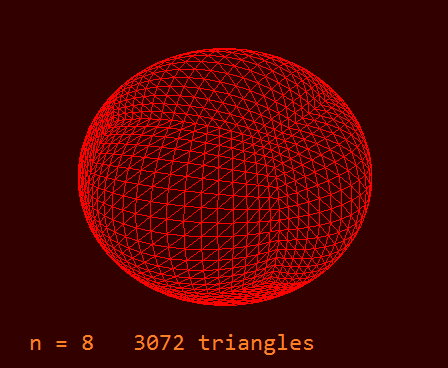
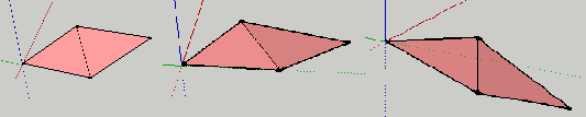
What's next?
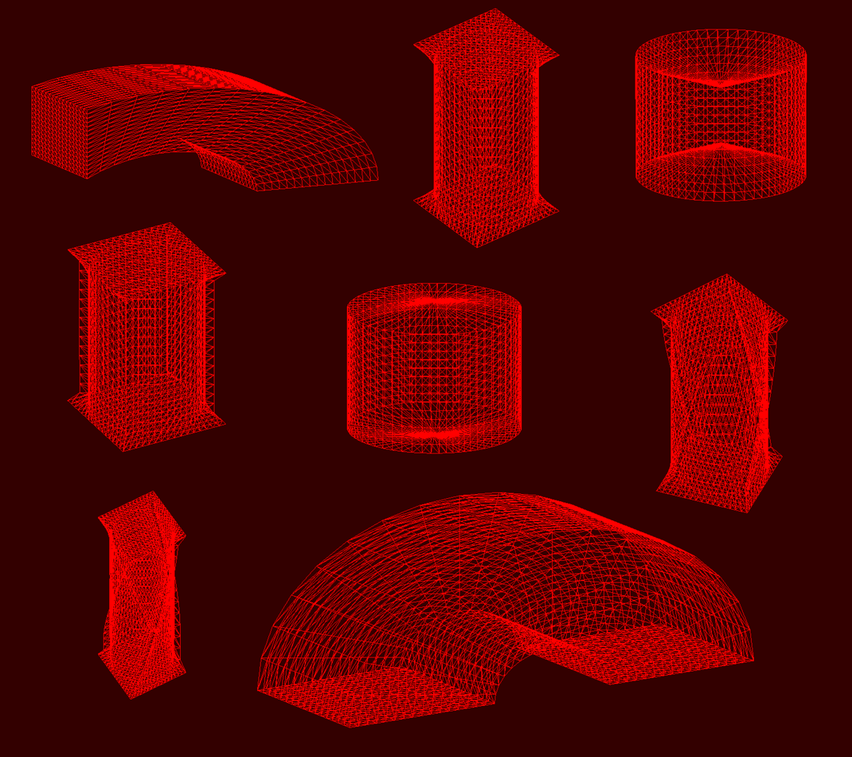
Now that we have the cube mesh what we can do with with it practically unlimited. The first thing I did was turn it into a sphere. Playing with tesselating the cube or sphere or stellating it with different patterns; might do. Ended up trying a few matrix transformations on the cube mesh. These are shown in the image below.
These shapes are result short bits of code like the code for the column shape below.
//Column
    for(int i = 0; i < number_of_triangles; i++){
        for(int j = 0; j < 3; j++){
            if( glTriangle[i].vert[j].y < 0.5f  && glTriangle[i].vert[j].y  > -0.5f  ){
            float length_of_v = sqrt((glTriangle[i].vert[j].x * glTriangle[i].vert[j].x) + (glTriangle[i].vert[j].z * glTriangle[i].vert[j].z));
            glTriangle[i].vert[j].x = 0.5f*glTriangle[i].vert[j].x/length_of_v;
            glTriangle[i].vert[j].z = 0.5f*glTriangle[i].vert[j].z/length_of_v;
            }
        }
    }
Doing this; the blacksmith at his forge analogy soon presents. The mesh is the ingot, hammer matrices stretch, round and bend it against the fixed geometry of the anvil - coordinate system. I am the smith.
Tetrahedron
The tetrahedron is the platonic solid with the least number of faces(4), edges(6), and verts(4). In antiquity it was associated with the element of fire due to its' sharp vertices. The algorithm for the tetrahedron mesh was developed in a similar way to the cube, but here it seemed simpler to get a routine for just one face - an equilateral triangle - and use matrix translations and rotations to form the complete tetrahedron. So more like origami or tinsmithing than blacksmithing.
Procedural tetrahedron screenshot.
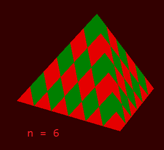
The n = 4 and the general case
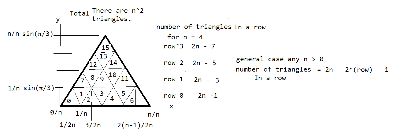
To get an routine for the general case, n an integer > 0, a bit of what I think is known as mathematical induction was used.
PSUEDO-CODE

Algorithm to generate equilateral triangle face with
unit side composed of n² "sub-triangle" in the xy plane.

std::vector<Triangle> equilateral(int n){

	std::vector<Triangle> tri_Angle(n²);

// Create the seed triangle in xy plane .
// This is triangle "0" in the image above.
// This is in the xy(z=0) plane so all the
// tri_Angle.vert[0 thrue n  -1 ].z = 0.
// We just work with the x and y verts.

	tri_Angle[all].vert[all].z = 0;

	// The seed triangle
	tri_Angle[0].vert[0].x = 0;				tri_Angle[0].vert[0].y = 0;
	tri_Angle[0].vert[1].x = 1/2n;			tri_Angle[0].vert[1].y = sin(π/3)/n;
	tri_Angle[0].vert[2].x = 1/n;			tri_Angle[0].vert[2].y = 0;

	// Build the equilateral triangle face.
	int count(0);
	for(int row = 0; row < n; row++){
		count = 0;
		Spin = glmRotateMatrix( π/3, zaxis );

		// The magic happens here!
		for(int i = 2*n*row - row*row; i < 2*n*row - row*row + 2*n - 2*row - 1; i++)
		{
			if (count % 2 == 0 ) // Triangle is even in the row - just translate
			{
								// more magic.
				x_Lat = glm_Matrix((count + row)/2n, row*sin(π/3)/n, 0.0f);

				tri_Angle[i].vert[0] = x_Lat* tri_Angle[0].vert[0];
				tri_Angle[i].vert[1] = x_Lat* tri_Angle[0].vert[1];
			}
			else // Triangle is odd in the row - rotate then translate
			{
								//and more magic.
				x_Lat = glm_Matrix((count + row + 1)/2n, row*sin(π/3)/n, 0.0f);

				tri_Angle[i].vert[0] = x_Lat*Spin*tri_Angle[0].vert[0];
				tri_Angle[i].vert[1] = x_Lat*Spin*tri_Angle[0].vert[1];
			}
		}
			count++;
	}

	return tri_Angle;
}
This is the psuedocode version of the routine which generates the verts for the n² triangles in a face. Getting this algorithm was a bit of a brain drain but looking for patterns in the image of the face allowed it to happen. We use a "seed" triangle, which is triangle 0 on the lower left of the figure. The verts of this one triangle are input; the rest of the n² triangles verts are generated by translating and rotating this seed triangle.
Notice: There are n rows, every row has 2 less triangles than the row below. If we number the triangles from 0 to 2n - 2*row - 2, where the rows run 0 to n; the even triangles just need to be translated ...
in the x direction by (count + row)/2n where count = their position in the row 0 to 2n - 2*row - 2.
in the y direction by row*height. height = height of seed triangle.
The odd triangles need to be rotated pi/3 = 60 degrees around the z axis then translated ...
in the x direction by (count + row + 1)/2n where count = their position in the row 0 to 2n - 2*row - 2.
in the y direction by row*height. height = height of seed triangle.
Now we have a single face for the tetrahedron, to join the four faces together we need the angle between the faces called the dihedral angle.
Dihedral Angle
Each of the five platonic solids has a characteristic called the dihedral angle. This is the angle between the faces. For the cube it is 90 degrees or pi/2 radians. For the tetrahedron it is 70.528779° = arccos(1/3) = atan(2*sqrt(2));
The tetrahedron, with just four faces, is the simplest of the platonic solids.
The simplest way I can think of to build it: Start with the four face stacked one on another, edges aligned. Imagine the top three faces each hinged to the bottom face along one edge. Then rotate each face around then hinged edge by arccos(1/3), the dihedral angle. That is the method of the bit of code shown below.
vector<Triangle> tetrahedron(int N){

	std::vector<Triangle> tetra(4n²);

	tetra[all].vert[all].z = 0;

	// The seed triangle
	tetra[0].vert[0].x = 0;			tetra[0].vert[0].y = 0;
	tetra[0].vert[1].x = 1/2n;		tetra[0].vert[1].y = sin(π/3)/n;
	tetra[0].vert[2].x = 1/n;		tetra[0].vert[2].y = 0;

// -----  The first face  -----
// generate the first equilateral triangle face with unit side
// composed of n² "sub-triangle" in the xy(z=0) plane.
	int count(0);
	for(int row = 0; row < n; row++)
	{
		count = 0;
		Spin = glmRotateMatrix( π/3, zaxis );

		for(int i = 2*n*row - row*row; i < 2*n*row - row*row + 2*n - 2*row - 1; i++)
		{
			if (count % 2 == 0 ) // Triangle is even in the row - just translate
			{
				x_Lat = glm_Matrix((count + row)/2n, row*sin(π/3)/n, 0.0f);

				tetra[i].vert[0] = x_Lat* tetra[0].vert[0];
				tetra[i].vert[1] = x_Lat* tetra[0].vert[1];
			}
			else // Triangle is odd in the row - rotate then translate
			{
				x_Lat = glm_Matrix((count + row + 1)/2n, row*sin(π/3)/n, 0.0f);

				tetra[i].vert[0] = x_Lat*Spin*tetra[0].vert[0];
				tetra[i].vert[1] = x_Lat*Spin*tetra[0].vert[1];
			}
		}
			count++;
	}

// -----  The second face  -----
// generate the second equilateral face from the first
// by rotating around the X axis by the dihedral angle.

	float tetra_Dihedral = atan(2*sqrt(2));

	Spin = glmRotateMatrix( -tetra_Dihedral, xaxis );  //just rotate
	for(int i = 0; i < n²; i++)
	{
		for(int j = 0; j < 3; j++)
		{
			tetra[n² + i].vert[j] = Spin*tetra[i].vert[j];
		}
	}

	//The rotation gives CCW verts so need need to make them CW again
	for(int i = n²; i < 2n²; i++)
	{
		swap(tetra[i].vert[0] ---- with --- tetra[i].vert[2];
	}

// -----  The third face  -----
// For the second face we rotated the first triangle around its'
// base on the X - axis. For the third face we rotate the first
// triangle around its' edge along the vector ( 0.5, 0.866025, 0.0 ).

	Spin = glmRotateMatrix( tetra_Dihedral ,glm::vec3(0.5f,0.866025f,0.0f));
	for(int i = 0; i < n²; i++)
	{
		for(int j = 0; j < 3; j++)
		{
			tetra[2n² + i].vert[j] = Spin*tetra[i].vert[j];
		}
	}

	//need to make it CW again
	for(int i = 2n²; i < 3n²; i++)
	{
		swap(tetra[i].vert[0] ---- with --- tetra[i].vert[2];
	}

// -----  The forth face  -----
// For the forth face we first translate the original face along the
// X axis so it right edge vector (-0.5f, 0.866025f, 0.0f) passes thru the origin.
// Then we rotate the first triangle around the that vector by the dihedral angle.

	x_Lat = glm::translate( glm::vec3(-1.0f, 0.0f, 0.0f));
	Spin = glmRotateMatrix( -tetra_Dihedral, glm::vec3(-0.5f,0.866025f,0.0f));
	for(int i = 0; i < n²; i++)
	{
		for(int j = 0; j < 3; j++)
		{
			tetra[3n² + i].vert[j] = Spin*x_Lat*tetra[i].vert[j];
		}
	}
	//need to make it CW again
	for(int i = 3n²; i < 4n²; i++)
	{
		swap(tetra[i].vert[0] ---- with --- tetra[i].vert[2];
	}

// We now have the complete tetrahedron, tetra(4n²), but its' base
// is not horizontal so let's make is so.


	// put the base in the xz plane
	// rotate 90 - dihedral angle around X axis.

	Spin = glm::rotate( tetra_Dihedral - half_PI, xaxis);
	for(int i = 0; i < 4n²; i++)
	{
		for(int j = 0; j < 3; j++)
		{
			tetra[i].vert[j] = Spin*tetra[i].vert[j];
		}
	}

// We now have the complete tetrahedron, tetra(4n²), sitting with its'
// base on the xz(y=0) plane, let's put its' center at the origin.
// For this we need another Platonic Solid attribute: The radius of
// the tetrahedrons circumscribed sphere which is sqrt(3/8).  So the
// center of the tet is this vertical distance down from its' apex.
// To put the center at the origin we need to translate down this
// distance along the Y axis. We need also to xlat along the Z axis
// by 1/2(sqrt(3)) = 0.28867; the distance from the center of a face
// to the center of a side.
// Finally we need to center along the X axis( xlat -.5)

	x_Lat = glm::translate( glm::vec3(-0.5f, -sqrt(3/8), sqrt(3)/2);
	for(int i = 0; i < 4n²; i++)
	{
		for(int j = 0; j < 3; j++)
		{
			tetra[i].vert[j] = x_Lat*tetra[i].vert[j];
		}
	}

	return tetra;
}
Notes:
Oops: Left out std::vector<Triangle> tri_Angles(4*n*n); Should be the first line of the function body!
Corrections to the corrections: First line of function definition
vector<Triangle> tetrahedron(int N){ should be
vector<Triangle> tetrahedron(int n){
Those last two for loops could and probably should be combined to do a translate*rotate*triangle in one statement, but I have not tried it.
All distances are for a tetrahedron with unit side.
The sign of the dihedral angle in the rotations was usually determined by trial and error. I.e.; I tried one sign, compiled the code and rendered the tet. If it was wrong I just reversed the sign.
The end result is a tetrahedron with its' center at the origin, its' base in the xz plane, and one edge parallel to the X axis.
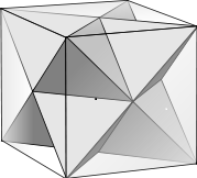
Of the five platonic solids; three (tetrahedron, octahedron, icosahedron) are composed of equilateral triangle faces. One of square faces (cube). And one of pentagon faces (dodecahedron).
Two tetrahedrons fit nicely in a cube.
11-16-18: Corrections to code blocks for equilateral triangle and tetrahedron.
11-18-18: More corrections.
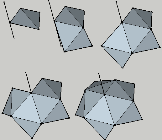
Icosahedron
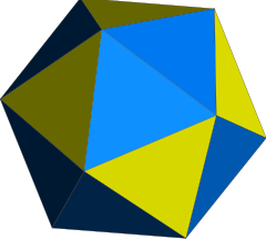
Two faces = Icosahedron Petal
Five petals in this flower = 10 faces = half of the icosahedron
12-5-18
Understanding the icosahedron's 3d form via 2d images is difficult; we need to make a small, palm sized, 3d model. It takes nineteen paper triangles and some tape. The vertices of five equilateral triangles must come together at each vertex of the icosahedron. The icosahedron has 20 faces and 12 verts, but leaving one face off the model allows us to look in side. Besides; when where done we'll have a neat little icosahedron basket. You don't really need to make a model to code the icosahedron; but it helped me to see some properties which simplified its' construction.
Symmetries are important to the mathematician and perhaps even more so to the physicist. They say something has a certain symmetry if you perform a certain operation on it and the world remains unchanged. Unchanged in the sense that you can not even detect something has been done to it. Example: Rotate a square 90 degrees around its center in the plane; the square has that type of rotational symmetry. The square also has an inversion symmetry; if you take every point on the square and invert it through the origin you end up with the same square you started with. Inversion is simply negating all the coordinates. The center must be at the origin of course. This is true for the cube, but not for the tetrahedron.
Symmetries simplify the construction (coding) of an object. Going back to the cube; it might have been easier to do three faces and then just invert them thru the origin to get the other three. For the tetrahedron simple inversion is not a symmetry, but I am pretty sure inversion together with a rotation is. If so; we could do two faces and then perform an inversion - rotation on them in one step. And inversion in Cartesian coordinates just means to negate all the verts - easy!
Toying with our icosahedron model; holding it gently with our thumb on one vertex and our middle finger on the opposite vertex, lazily twirling it around an imaginary axis through those two vertices; we are struck with a thought: We are toying with our icosahedron model twirling it around an axis through - Eureka! - two opposite vertices: The icosahedron has inversion symmetry. This is great - our work has just been cut in half. We can code half of the icosahedron's verts and just invert(negate) to get the rest. Thank you inversion symmetry. But let's not stop now, we are on a roll (no pun intended); let's see if we can find more symmetries to make our work easier. Looking intently; holding our model as before, but still, not rotating. Then slowly rotating about the axis we see another symmetry. After one fifth of a revolution(2π/5 radians) the universe looks the same as when we started rotating it. The icosahedron has a 2π/5 rotational symmetry. Can we use this to cut our work load? You bet we can.
First we need to clear up a few points about something central to our construction efforts: The axis of symmetry. (Sorry, the puns just keep coming.) An axis of symmetry is a line passing thru two opposite vertices and the center of the icosahedron. The icosahedron has six of them: We only need one. We will use the Z axis.
Dihedral angle: To be precise, it is the angle between the normals of two adjacent faces.
The images:
Looking at the images we see a flower shape with five "petals". A petals is just two faces joined along a side. The angle between the two petal faces is the icosa's dihedral angle; arccos(- √5/3) radians. Five petals make a "flower" , which is ten faces, so it is half of the icosahedron. Once we have five petals joined to make this flower, we just copy/invert all its' verts to get the other half: We have our icosahedron.
The Plan: Refer to the figures
1.) Make a petal.
2.) Attach one tip of the petal the axis of symmetry.
(Oriented properly of course.)
3.) Copy/rotate the petal around the axis of symmetry
by 2π/5 radians four times to get five petals = a flower.
We are using the 2π/5 radians rotational symmetry here.
4.) Copy/invert( r -> -r ) our five-petal-ten-face flower to get
our 20 face icosahedron. Using inversion symmetry here.
So just four steps; sounds simple enough. Each step has its own steps of course, but they are mostly intuitive common sense things we must do to get the result.
Constants:
Before we get to the code we need four constants.
1.) The dihedral angle between two faces, the dihedral_angle.
dihedral_angle. = arccos(- √5/3) = 46.06322 radians = 138.18969°.
2.) The angle between the Z axis and the normal of a face of a petal at the vertex. 0.652351 radians
3.) The radius of a circumscribed sphere(A sphere that touches all 12 verts). In other words the distance from the icosahedron center to a vertex. Also called the circumradius.
R = sin(2π/5).
4.) The rotational symmetry: 2π/5 radians
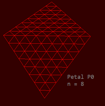
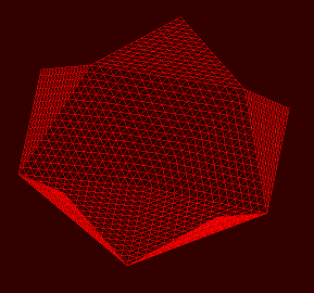
Let's not do a blow by blow, or should say, a bend by bend, description of the code. If a picture is worth a thousand words, it seems safe to assume an animated 3D image is worth even more. I suggest we compile the code and render to the display step by step. In fact this is how the code was developed; with a projection matrix and a rotation around the Z axis.
Compile - Render the first face: F0.
" " the first petal: P0 from F0 and F1.
" " the second petal P1.
" " the third petal P2.
" " the fourth petal P3.
" " the fifth petal P4.
We now have the flower.
Compile - Render the inversion of the flower.
Done.
The icosahedron pseudocode.
struct Triangle
{
	glm::vec3 vert[3]; // the three verts of the triangle
};

//PSUEDOCODE ICOSAHEDRON
/*  input:	integer n - number of triangles along
			icosahedron edge.

	output: std::vector<Triangle> icosahedron - mesh
			with 20n² triangles.
*/

std::vector<Triangle> icosahedron( int n ){

	const float dihedral_Angle = acos(-(sqrt(5.0f)/3.0f));
	const float dihedral_Comp = π - dihedral_Angle;

    std::vector<Triangle> T_icosahedron(20n²);

// Create the seed triangle T.
	Triangle T;
	T.vert[0].x = 0;			T.vert[0].y = 0;			T.vert[0].z = 0;
	T.vert[1].x = 1/2n;			T.vert[1].y = sin(π/3);		T.vert[1].z = 0;
	T.vert[2].x = 1/n;			T.vert[2].y = 0;			T.vert[2].z = 0;

// ----- F0 -----
// Create the first face; "F0" in the xy(z=0) plane
// from the seed triangle T.

	int count(0);
	for(int row = 0; row < n; row++){
		count = 0;
		for(int i = 2*n*row - row*row; i < 2*n*row - row*row + 2*n - 2*row - 1; i++){

			if (count % 2 == 0 ){ // Triangle is even in the row - just translate .
				x_Lat = glm::translate(count+row)/2n, row*sin(π/3), 0);
				for(int j = 0; j < 3; j++){
					T_icosahedron[i].vert[j] = x_Lat*T.vert[j];
				}
			}
			else{ // Triangle is odd in the row - rotate then translate.
				x_Lat = glm::translate( glm::vec3((count+1+row)/2n, row*sin(π/3), 0));
				Spin = glm::rotate( π/3, zaxis );
				for(int j = 0; j < 3; j++){
					T_icosahedron[i].vert[j] = x_Lat*Spin*T.vert[j];
				}
			}
			count++;
		}
	}

// At this point comment out the rest of the code,
// return T_icosahedron;
// Compile and render F0 to the display.

// ----- P0 -----
// Create the first petal "P0" in the xy(z=0) plane.

	glm::vec3 axis(0.5f, sin(π/3), 0.0f);
	Spin = glm::rotate(  π/3, zaxis );  //just rotate
	Spin2 = glm::rotate(  -dihedral_Comp, axis );
	for(int i = 0; i < n²; i++){
		for(int j = 0; j < 3; j++){
			T_icosahedron[n² + i].vert[i] = Spin2*Spin*T_icosahedron[i].vert[j];
		}
	}

// xlate P0 by -1.0 along x and bend down by epsilon from the xy plane
// epsilon is the angle we want between the Z axis and the normal of F0.
// epsilon = 0.6523581f;

	x_Lat = glm::translate( glm::vec3(-1.0f, 0.0f, 0.0f));
	Spin2 = glm::rotate( glm::mat4(1.0), -π/3, zaxis );
	Spin = glm::rotate( glm::mat4(1.0), -epsilon, xaxis );  //just rotate
	for(int i = 0; i < 2n²; i++){
		for(int j = 0; j < 3; j++){
			T_icosahedron[i].vert[j] = Spin*Spin2**x_Lat*T_icosahedron[i].vert[j];
		}
	}

// At this point comment out the rest of the code,
// return T_icosahedron;
// Compile and render P0 to the display.

// Create P1 from the P0 verts, rotate 2π/5 around z then

	Spin = glm::rotate( 2π/5, zaxis );  //just rotate
	for(int i = 0; i < 2n²; i++){
		for(int j = 0; j < 3; j++){
			T_icosahedron[i+2n²].vert[j] = Spin*T_icosahedron[i].vert[j];
		}
	}

// At this point comment out the rest of the code,
// return T_icosahedron;
// Compile and render P0 - P1 to the display.


// Create P2 thru P4 from P0 verts: rotate around z:
// 2*2π/5 for P2, 3*2π/5 for P3 and finally 4*2π/5 for P4

	// P2
	Spin = glm::rotate(  2*2π/5, zaxis );  //just rotate
	for(int i = 0; i < 2n²; i++){
		for(int j = 0; j < 3; j++){
			T_icosahedron[i+4n²].vert[j] = Spin*T_icosahedron[i].vert[j];
		}
	}
	// P3
	Spin = glm::rotate(  3*2π/5, zaxis );  //just rotate
	for(int i = 0; i < 2n²; i++){
		for(int j = 0; j < 3; j++){
			T_icosahedron[i+6n²].vert[j] = tSpin*T_icosahedron[i].vert[j];
		}
	}
	// P4
	Spin = glm::rotate(  4*2π/5, zaxis );  //just rotate
	for(int i = 0; i < 2n²; i++){
		for(int j = 0; j < 3; j++){
			T_icosahedron[i+8n²].vert[j] = Spin*T_icosahedron[i].vert[j];
		}
	}

// At this point we should have the full flower.
// Comment out the rest of the code,
// return T_icosahedron;
// Compile and render P0 thru P4 to the display.

	// Move everthing up along z to put the icosahedron center at the origin.
	// radius of circumscribed sphere = sin(2π/5), for face side = 1.
	x_Lat = glm::translate( glm::vec3(0, 0, sin(2π/5));
	for(int i = 0; i < 10n²; i++){
		for(int j = 0; j < 3; j++){
			T_icosahedron[i].vert[j] = x_Lat*T_icosahedron[i].vert[j];
		}
	}

// invert all the verts and reverse for cw winding
// this creates the other half of the icosahedron from the first 10 triangles
	for(int i = 0; i < 10n²; i++){
		for(int j = 0; j < 3; j++){ // invert
			T_icosahedron[i+10n²].vert[j].x = -T_icosahedron[i].vert[j].x;
			T_icosahedron[i+10n²].vert[j].y = -T_icosahedron[i].vert[j].y;
			T_icosahedron[i+10n²].vert[j].z = -T_icosahedron[i].vert[j].z;
		}
		// Swap verts 0 and 2 to get back to CW winding.
		hold = T_icosahedron[i+10n²].vert[0];// reverse
		T_icosahedron[i+10n²].vert[0] = T_icosahedron[i+10*n²].vert[2];
		T_icosahedron[i+10n²].vert[2] = hold;
	}

return T_icosahedron;

// Spherify - uncomment the code below to spherify the icosahedron
/*
	for(int i = 0; i < 20n²; i++){
		for(int j = 0; j < 3; j++){
			float length_of_v = sqrt(
				(T_icosahedron[i].vert[j].x * T_icosahedron[i].vert[j].x) +
				(T_icosahedron[i].vert[j].y * T_icosahedron[i].vert[j].y) +
				(T_icosahedron[i].vert[j].z * T_icosahedron[i].vert[j].z));
		   T_icosahedron[i].vert[j].x = T_icosahedron[i].vert[j].x/length_of_v;
		   T_icosahedron[i].vert[j].y = T_icosahedron[i].vert[j].y/length_of_v;
		   T_icosahedron[i].vert[j].z = T_icosahedron[i].vert[j].z/length_of_v;
		}
	}
*/

	return T_icosahedron;
}
Screen-shots: First petal P0 and five petal icosahedron flower.
19 December 2018
There are just two Platonic solids left to render; the octahedron and the dodecahedron. It is obvious, even from a two dimensional image, that the octahedron has an axis of symmetry and is both inversion symmetric and rotation symmetric about that axis. I needed another three dimension model to realize the same is true for the dodecahedron. We can adapt the icosahedron algorithm to model both of these solids:
Create a petal
octahedron - 2 triangles
dodecahedron - 2 pentagons
Create a flower
Copy/rotate around the axis
octahedron - 4 petals - π/2 radians
dodecahedron - 3 petals - 2π/3 radians
Copy/invert the flower
Notice: Dodecahedron only!
The way forward is clear - we adapt our icosahedron procedure. We make our petals. We use the same 4 constants; dihedral angle,
rotational symmetry angle, angle between petal face and axis, circumscribed sphere radius (different values of course). We iterate our petal copy-rotations, 4-times for the octahedron, 3-times for the dodecahedron. We are done with the octahedron at this point. Four petals around its axis forms the complete closed solid; more an unopened flower bud than a flower. We invert the dodecahedron. We put the centers of the solids at the origin.
That is the work plan in a nutshell. Implementing the code will now be routine - the only new thing is working with pentagon faces
for the dodecahedron. These pentagon faces will be composites of five triangle faces. We already have an algorithm for the triangle faces so just need to create a routine to join five together to make the pentagon.

Was there more to your blog? It looks like you have the heading started 'Dihedral Angle' but no content under it.