Advertisement

Calculate angles to render 3D actor as an affine-transform sprite

Started by November 09, 2024 11:07 PM
11 comments, last by Aikku 6 hours, 31 minutes ago

For a bit of background: I'm working on a tech demo for the Gameboy Advance, where I'm using pre-rendered backgrounds - combined with a 3D navmesh, and a camera matrix - to place actors into the scene. Because the GBA doesn't have any 3D hardware, my plan is to pre-render the actors from many different angles (eg. 8 angles around the global up/down axis, and 4 angles around the global left/right axis), and then choosing the correct angles for display. Note that rotation about the camera z axis doesn't need pre-rendering, as I can do this using the GBA hardware directly, provided that this is the last rotation (all I need is the sine/cosine terms).

And now for the part I'm stuck on: If you are given the camera matrix (which in my case consists of an orthogonal 3x3 view matrix, plus a translation vector and FOV + viewport scaling factor), how do you deduce which angles to use for displaying the actor?

For example: if my actor sprite sheets are arranged as an array like [GlobalRotX=0..3][GlobalRotY=0..7], and the final rotation about the camera z axis accepts an angle theta, then given the actor position pos_char.xyz and local rotation rot_char.xyz, how do I calculate GlobalRotX, GlobalRotY, and theta? To make things easier to explain, you can just assume that GlobalRotX/Y and theta are all in the range -Pi..+Pi or whatever - I just need to be able to understand the maths behind this, rather than bogging things down with implementation details.

My first thought had been to find the camera position in world space (by multiplying the negated translation vector by the inverse/transpose of the 3x3 view matrix), then somehow use an atan2 with the camera position and the actor position, but this feels wrong and incomplete. For example, if the camera has a rotation about the forwards/backwards axis, this wouldn't be taken into account, I think.

Any help would be greatly appreciated. I've tried searching a fair bit, but everything I've found involving angle extractions seems to assume that you are generating sequential transformations from that information (which is most definitely not what I'm doing), and I'm just not that good at this kind of maths to be able to unravel what is actually going on in there.

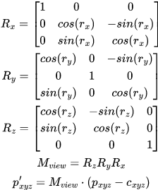
I get the feeling I'm just missing (and maybe misusing?) some terms. So to maybe clarify and simplify to maths directly, here's the situation:

where c_xyz is the camera position (in world coordinates), p_xyz is some position to transform (in world coordinates), and M_view is the camera view matrix (composed only of standard x→y→z rotation matrices, with no shears or scaling).

  1. Given only M_view and c_xyz, is there a unique solution to r_z?
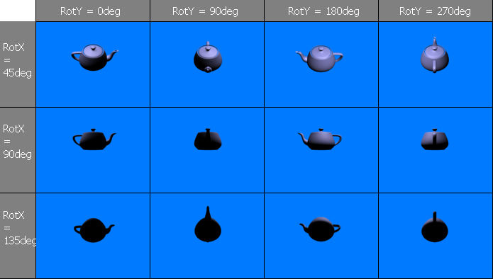
  2. If I pre-render a 3D object from a bunch of different angles (see below picture), then is it possible to find the correct angle to choose from in a sprite sheet, using only M_view, p_xyz, and c_xyz?

The sprite sheet might look something like this, for reference:

Advertisement

You're making this sound very complicated (no offense), so maybe I'm misunderstanding something… but the way I'd solve this, is by constructing my camera-matrix using a LookAt-function (https://learn.microsoft.com/en-us/windows/win32/direct3d9/d3dxmatrixlookatlh) - I've got no better reference, but any rendering-library should have one, and there should be ton of implementations available if you need one yourself. Then, the only relevant parameters are the object and camera-position. You position the camera at a certain offset to the object (ie. vObject + {1.0f, 0.0f, 0.f}), and then you just rotate the vector around two discrete axis for all the permutations of RotX and RotY. For example, rotate around {0.0, 1.0f, 0.0f} for rotY first, and then around the normal-vector for the plane described by the newly rotated vector and the up-axis for rotX.
Let me know if the math-part with the rotation is unclear, but I think you should be able to figure that out. The more important factor is reducing the complicated computation that you described into a more simplified LookAt-function.

As for finding the matching sprite - just build a “matrix” with rotX and rotY as row/column, then calculate the two angles used to construct the view-matrix, from the current vector between object and camera, and use the clostest match (ie. x = rotX / 45, y = rotY / 45).

Aikku said:
Given only M_view and c_xyz, is there a unique solution to r_z?

If I pre-render a 3D object from a bunch of different angles (see below picture), then is it possible to find the correct angle to choose from in a sprite sheet, using only M_view, p_xyz, and c_xyz?

Yes and yes, if i understand you correctly.
I'm sure what you want is possible, but idk what's your specific problem and how we could help.

However, the problem is equivalent to the problem of converting a 3D rotation to euler angles and their given order, and vice versa.
I have soem code for that:

 	__forceinline void FromEuler (const sVec3 &radians, const int order = 0x012) 
	{
		int a[3] = {(order>>8)&3, 
					(order>>4)&3, 
					(order>>0)&3};

		sMat3 r[3] = {	rotationX (radians[0]),
						rotationY (radians[1]),
						rotationZ (radians[2])};

		(*this) = r[a[0]];
		(*this) *= r[a[1]];
		(*this) *= r[a[2]];
	}

	__forceinline sVec3 ToEuler (const int order = 0x012) 
	{
		int a0 = (order>>8)&3;
		int a1 = (order>>4)&3;
		int a2 = (order>>0)&3;

		sVec3 euler;
		float d = (*this)[a0][a2];
		// Assuming the angles are in radians.
		if (d > (1.0f-FP_EPSILON)) 
		{ // singularity at north pole
			euler[a0] = -atan2f((*this)[a2][a1], (*this)[a1][a1]);
			euler[a1] = -3.1415926535897932384626433832795f/2.0f;
			euler[a2] = 0;
			return euler;
		}
		if (d < -(1.0f-FP_EPSILON))
		{ // singularity at south pole
			euler[a0] = -atan2f((*this)[a2][a1], (*this)[a1][a1]);
			euler[a1] = 3.1415926535897932384626433832795f/2.0f;
			euler[a2] = 0;
			return euler;
		}
		euler[a0] =	-atan2f(-(*this)[a1][a2], (*this)[a2][a2]);
		euler[a1] =	-asinf ( (*this)[a0][a2]);
		euler[a2] =	-atan2f(-(*this)[a0][a1], (*this)[a0][a0]);
		return euler;
	}

Those are member methods of a 3x3 matrix class, accessing the matrix values with [][], and using OpenGL convention.

If your matrix is the camera orientation, the 3 euler angles (you use only 2) calculated from ToEuler() could be used to index the sprite sheet.
The given order would describe your convention of the sheet, regarding which axis is rotated first.
My function takes a hex number for that, where 0x012 means XYZ order, and 0x120 means YZX order for example.

I might miss some detail, but i'm pretty sure it is that simple once you have figured it out after a lot of trial and error.
Beside the 6 potential orders, things that gave me a solution in the past where: Transposing the matrix, and negating the returned angles, eventually. That's lots of options, so frustration is expected. I'm pretty good with 3D rotations, but the knowledge did not help much when dealing with evil euler angles. ; )

I usually avoid using angles because they complicate matters and don't behave nicely near “poles” and “gimbal locks".

Here's what I would try. Represent the attitude of your object using a quaternion, w + xi + yj + zk. Your rendering library can do 2D sprite rotations, so you don't need to have multiple views for rotations that differ only on the z value. That means you can arbitrarily set z=0 and try to get a representative grid of rotations where only w, x and y change. Pick the coordinate with the largest absolute value and divide all of them by it. Let's say, as an example, that x was the one with the largest absolute value. The values of w and y are now both between -1 and 1. So take the [-1,1]x[-1,1] square and put a grid on it. Let's say you use a 4x4 grid. For simplicity, let's start using the values {-0.75,-0.25,0.25,0.75} for w and y.

So this gives you a total of 3 x 4 x 4 pre-rendered sprites ("3" here is encoding what coordinate had the largest absolute value), corresponding to the quaternions

  • 1 + Ai + Bj,
  • A + i + Bj,
  • A + Bi + k

where A and B are in {-0.75,-0.25,+0.25,+0.75}.

Those four values are not optimal, but they are simple. You may want to make sure you include 0 in your list of values, if for some reason it's important to get 90-degree rotations exactly right.

If my explanation doesn't get you to being able to produce code, let me know and I'll post something.

Thanks for the replies!

You're making this sound very complicated (no offense), so maybe I'm misunderstanding something… but the way I'd solve this, is by constructing my camera-matrix using a LookAt-function […]

If I understood your reply correctly, then that's not the problem I'm having. I can pre-render the objects in the way you described, that part's easy enough. My problem is trying to choose the correct sprite at run-time, given only the camera matrix and position. There just isn't enough CPU to render the 3D objects at run-time, unfortunately, since actor models generally need at least 100-200 triangles, which completely blows my CPU budget (even 64 triangles got me down to around 10fps, and I'll need to display a lot more than one actor).

However, the problem is equivalent to the problem of converting a 3D rotation to euler angles and their given order, and vice versa.
I have soem code for that:

Awesome, thanks! I'll take a look once I get back home from work (in about 13 hours from now).

I usually avoid using angles because they complicate matters and don't behave nicely near “poles” and “gimbal locks".

I had vaguely thought about doing something like this, but I just still can't wrap my head around quaternions properly haha. If my very vague understanding of quaternions is right, then the possibly-similar vague idea I'd had was something along the lines of sweeping the camera along a spiral about the origin. Like I said though - I haven't been able to understand quaternions well enough to be able to make use of them, so I could be completely off-track as to that being similar.

But either way, though, the object also needs to rotate with regards to the camera position and orientation, which is the reason I'm asking for help here, because I wasn't able to figure out the correct angles to be using (or I guess in this case, the quaternion values, but I think there's plenty of example code for converting a 3x3 matrix into a quaternion).

Advertisement

I've finally had the chance to run some quick tests (more specifically, the extraction of the z rotation).

JoeJ said:

// ...
		euler[a2] =	-atan2f(-(*this)[a0][a1], (*this)[a0][a0]);
// ...

This seems to be /almost/ right, but there is an issue if the camera is facing towards -z (and I'm guessing the other angles have a similar issue, with the camera facing towards a different negative axis); I'm computing the sine/cosine terms from the parameters directly, and when the camera is facing -z, the cosine term comes out negated (equivalent to negating the atan2 x argument). Inspecting the Ry matrix for this case makes it pretty clear what is happening (Ry_00 gives a negative term that “contaminates” the atan2 result).

I've tried to think of a way to correct for this, but I'm drawing a blank here haha. I think inspecting M[a0,1,2][0] in tandem is required, but I'm not sure what the trick here would be. I'm unfortunately not very good at trigonometry, but it feels like there's something obvious here that I'm missing.

Don’t let quaternions scare you. The easiest way to understand them is as a blend of orientations that are as far apart as possible.

In 2D, the analog to quaternions is to use complex numbers instead of angles. The two orientations as far apart as possible are (1) where you started (the real part) and (2) rotated 180 degrees upside down (the imaginary part).


The only thing quaternions add to this is different ways of turning upside down. In 2D there is only one plane in which to rotate. In 3D, you can rotate by 180 degrees in the xy plane, the yz plane, or the zx plane. So there is a blend between not turning upside down, and three different ways to turn upside down… which is why quaternions have four parts.

There is a nice set of 24 unit quaternions which are spaced apart evenly, called the Hurwitz quaternions. This is a handy choice to use for a base bunch of orientations to render your object at.

If you have the quaternion representing the orientation at runtime, it is then easy to take a dot product between that orientation and all the orientations you have pictures for. Whichever dot product is the largest is the best pre-rendered picture to use!

Aikku said:
I've tried to think of a way to correct for this, but I'm drawing a blank here haha. I think inspecting M[a0,1,2][0] in tandem is required, but I'm not sure what the trick here would be. I'm unfortunately not very good at trigonometry, but it feels like there's something obvious here that I'm missing.

I can't imagine what your problem might be, but hacking the function probably isn't needed. Understanding how the function works probably isn't that helpful either, since imaginating 3 3D rotations in order is pretty hard for the human mind. The famous gimbal lock problem is an example for that, although it's more a myth than an actual problem imo.

I would do this: Use both functions to convert a rotation matrix to euler angles and then back to matrix. Just to verify the function works and ther is no bug which requires a fix. After that it's easier to focus on something else which might be the problem, e.g. given order not matching your desired convention, or inverting / transposing the matrix.
(If negative angles are not expeted, you can ofc. just make them positive using angle = 2Pi+angle.)

But if you have no luck, here's what i would do to figure it out on my own without any such black box functions:

Start with only one axis of rotation, like Doom sprites.
This should be somehow as simple as this, for example:

vec2 dir0 = normalize(npc.pos - camera.pos);
vec2 dir1 = npc.forwardDirection;

vec2 perp0 (-dir0.x, dir0.y); // perpendicular direction, so we can get the right sign of our angle
float realtiveAngle = atan2( dot(dir0, dir1), dot(perp0, dir1) );

const int spriteSheetResX = 36; // assuming we have the sprite rendered at 10 degree steps
int spriteSheetIndexX = (int)round(realtiveAngle / (2*PI) * spriteSheetResX);
if (spriteSheetIndexX < 0) spriteSheetIndexX += spriteSheetResX;

So this handles the rotation around the up vector, and it would pick the right image from the middle row of your pots example.

The second angle to select the proper image from the column showing the pot from slightly above should be like so:

const vec3 globalUp (0,1,0);// or (0,0,1)...

vec3 dir = npc.pos - camera.pos;
vec3 axis = normalize(cross(globalUp, dir)); // axis to rotate from the Doom view to the view from slightly above
vec3 front = cross(globalUp, axis); // direction on the ground plane pointing towards the camera

float angle = atan2( dot(globalUp, dir), dot(front, dir) );
// convert angle to sprite sheet row index as above...

I'm not 100% sure, but i think conceptually this should work.
Notice it's much more vector math than trig. Basically we construct two orthogonal basis vectors to define a 2D space, and then calculate the angle of a third direction in this space.
(The Look-At function mentioned earlier is another very good example for this, constructing the 3 basis vectors of a 3D orinetation using similar parctices.)

Advertisement