Advertisement

Scaling tessellation displacement with texture mapping

Started by September 12, 2024 11:00 PM
4 comments, last by JoeJ 4 months, 1 week ago

I am trying to make it so my displacement used with tessellation will scale with the texture mapping scale in global space. That is, if the texture is stretched across a big surface, the amplitude of the displacement should be bigger to match. Without this, the displacement can look flat or tall and skinny depending on the scale of the texture mapping. You can see in the shot below, the displacement is larger when the texture is spread across a bigger area, so the correct shape is preserved.
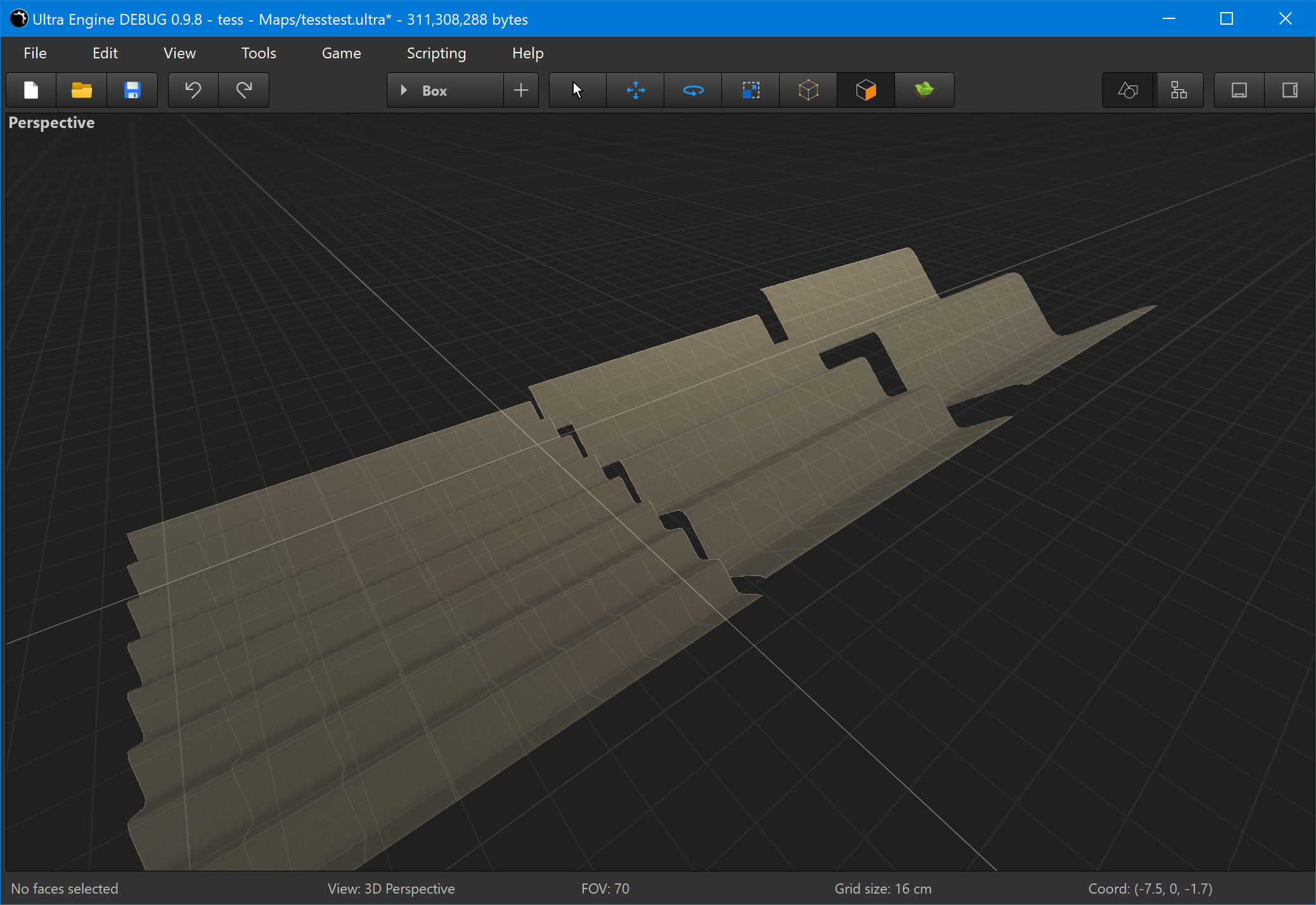
My first attempt was to calculate this in the tessellation evaluation shader, based on the edge lengths (position) divided by the edge length in texcoords. This works fine for flat surfaces like the shot above, but will produce cracks for curved surfaces like a sphere, where there is not a constant texture density.

My second attempt was to calculate this on the CPU and store it as a vertex attribute. This was a lot better, but some cracks are still visible. My vertex texture scale values are calculated as the average of all edges that vertex is part of, and it is not surprising there are some small differences.
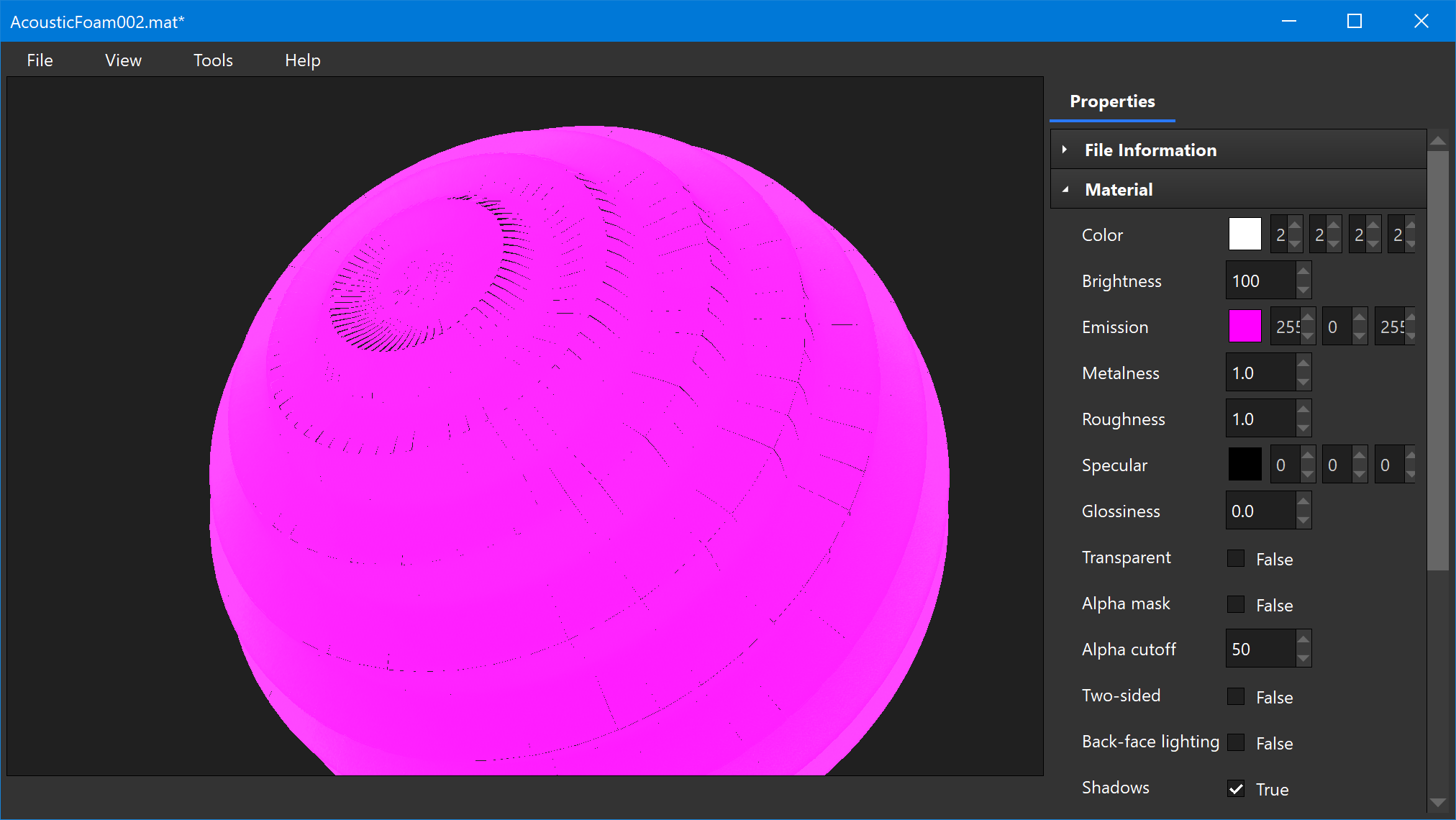
Is there any other technique I should think about? The only thing that seems like it would work for curved geometry is to just calculate an average texture mapping scale, and apply that to the whole mesh.

10x Faster Performance for VR: www.ultraengine.com

Josh Klint said:
but some cracks are still visible.

I'm a bit confused about what's your problem, since scaling alone can't fix the cracks.
To avoid cracks on a closed manifold such as a sphere, you would need a ‘seamless UV parametrization’, which is very hard to generate.
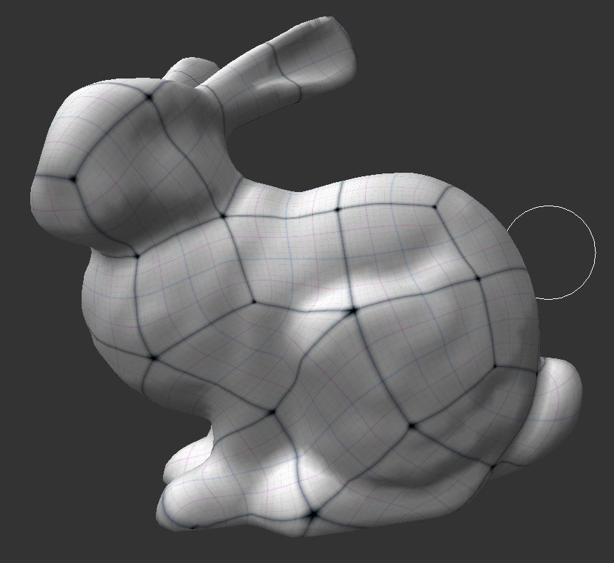
I've worked on this, here is an example on the bunny:

You see the surface is divided into quads without any triangles, and the quads all have the same size and stretch is minimized.
If we would make a quad mesh from this parametrization, we could apply crack free dispalcement mapping to bring it back to the initial shape with all the details. (As proposed in the geometry images paper, but they used low quality paramtrizations causing terrible stretchign artifacts.)

But even then we need to author individual texturing for each object. We can not use some generic bricks texture and apply it to the bunny. Becasue there are 90 degree rotations of UV space around irregular vertices (any vertices that has more or less than 4 edges), the rotated patch of texture would again not match at all its edges.

That's why displacement mapping can only be used for special cases where cracks are acceptable (terrain height maps, or manifolds where the UV seams are hidden below some geometry around the seam).

Maybe you were not fully aware of those limitations. Personally i was not, until i worked on this for other reasons. This is why displacement mapping never became as generally useful as we would like.

Advertisement

Texture alignment is a separate issue. I am only talking about meshes that already have perfectly aligned normals and texcoords right now.

We are crack-free until the displacement amplitude is adjusted to match the texture mapping scale. As shown in my first image, a texture stretched across a big area requires more displacement than a texture fit over a small area. At all three scales above, the displaced geometry forms the same 45 degree angles in the zigzag pattern.

The problem comes with something like a sphere, where you do not have an even texel density across adjacent polygons. You can see small hairline fractures near the center.

If I do not multiply the displacement amplitude by the texture mapping scale, no cracks can be seen.

My thinking right now is that polygons with non-orthographic texture mapping (the texture mapping axes do not form a right angle) then the only solution is to take an average texture mapping scale and apply it to the entire mesh.

When each polygon has orthographic texture mapping (the texture mapping axes form a right angle) then the texture mapping scale can safely be calculated in the evaluation shader.

Does anyone have a better idea than this?

10x Faster Performance for VR: www.ultraengine.com

Which Graphics-API are you using? If it's DirectX, I remember from my own terrain-tessalator, that there was some problem in the optimizer that would cause cracks on edges that are otherwise perfectly aligned. From looking in my repo, the needed fix was adding the following pragma to the tessalation-shader:

#pragma ruledisable 0x0802405f

Not sure it's actually the solution, but maybe worth giving it a shot (because if it is, how the hell is anyone supposed to figure this out, if they didn't accidentially used the Nvidia Terrain Tessalation Whitepaper as their tessalation-source, which mentioned this issue).

Ah i see. The cracks are not at texture seams, but everywhere.

Josh Klint said:
My first attempt was to calculate this in the tessellation evaluation shader, based on the edge lengths (position) divided by the edge length in texcoords.

I guess this causes inconstent results, e.g. sligthly different scales at the same vertex depending on which triangle you currently are at.

If you need to calculate the scaling factor per vertex, you would need have access to all edges adjacent to the vertex, not just the two from a single current triangle.
But i guess this data isn't accessible at this point, so a better way would be to use a vertex map generated offline.
Instead looking at edge lengths, you could work with triangle area on the geometry and in UV space. This might give smoother results in areas where stretching is high.

To do it procedurally while rendering, i don't see a way to make it work without having adjacency information of the mesh, which we usually don't have.

This topic is closed to new replies.

Advertisement