To answer your other questions: yes, the BRDF lookup texture will generally give you brighter results when viewing at grazing angles (dot(V, N) is close to 0). This is due to a combination of the Fresnel and geometry/visibility terms used in a microfacet BRDF, both of which cause the highlight to get more intense at grazing angles.
For a pure metal like copper it's true that the diffuse response should basically be 0. For your specular however you don't want to just “tint” the specular, you want use a proper specular albedo. Your specular albedo is usually known as the “F0” term, because it's the specular color you get when viewing at a head-on 0-degree angle (dot(V, N) == 1.0). You use this as an input to your fresnel term, which then causes the reflection to go to white at grazing angles. If you're doing pre-filtered environment lighting then you would do specAlbedo * lookupTexture.x + lookupTexture.y like I mentioned in my previous post. You should get something like this when doing that with a specAlbedo that's reddish-colored (I used (0.9, 0.53, 0.45):
Thanks very much for the detail posts MJP as always, that’s really explained everything perfectly.
To answer your other questions: yes, the BRDF lookup texture will generally give you brighter results when viewing at grazing angles (dot(V, N) is close to 0). This is due to a combination of the Fresnel and geometry/visibility terms used in a microfacet BRDF, both of which cause the highlight to get more intense at grazing angles.
For a pure metal like copper it's true that the diffuse response should basically be 0. For your specular however you don't want to just “tint” the specular, you want use a proper specular albedo. Your specular albedo is usually known as the “F0” term, because it's the specular color you get when viewing at a head-on 0-degree angle (dot(V, N) == 1.0). You use this as an input to your fresnel term, which then causes the reflection to go to white at grazing angles. If you're doing pre-filtered environment lighting then you would do specAlbedo * lookupTexture.x + lookupTexture.y like I mentioned in my previous post. You should get something like this when doing that with a specAlbedo that's reddish-colored (I used (0.9, 0.53, 0.45):
In that screenshot, are you using a direct light or is it just image based lighting? With just image based lighting, I can't get my grazing angles as bright as the light source in the environment map:
There was no direct lighting in that screenshot, just IBL. And I agree, what you have there does look too dark. I would probably try to debug that by stripping your shader code down to nothing but sampling the IBL cubemap, and making sure that it matches the intensity of the background. If it does, then you can add the other pieces back in and see where things went wrong. Also if you're generating the split-sum texture yourself, you might want to verify that looks right by comparing it against the image shown in the original UE4 paper. You can also try swapping it out for an analytical approximation that just uses shader code. I have one here you can drop in if you'd like: https://github.com/TheRealMJP/DXRPathTracer/blob/master/SampleFramework12/v1.02/Shaders/BRDF.hlsl#L209
There was no direct lighting in that screenshot, just IBL. And I agree, what you have there does look too dark. I would probably try to debug that by stripping your shader code down to nothing but sampling the IBL cubemap, and making sure that it matches the intensity of the background. If it does, then you can add the other pieces back in and see where things went wrong. Also if you're generating the split-sum texture yourself, you might want to verify that looks right by comparing it against the image shown in the original UE4 paper. You can also try swapping it out for an analytical approximation that just uses shader code. I have one here you can drop in if you'd like: https://github.com/TheRealMJP/DXRPathTracer/blob/master/SampleFramework12/v1.02/Shaders/BRDF.hlsl#L209
Got it! I was not clamping my LUT sampler so when using metalness of 1.0 it was actually wrapping and giving me the first LUT line. Clamping it gives me a much nicer effect - thanks MJP!:
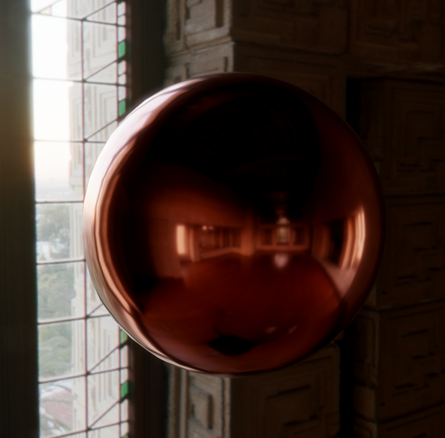
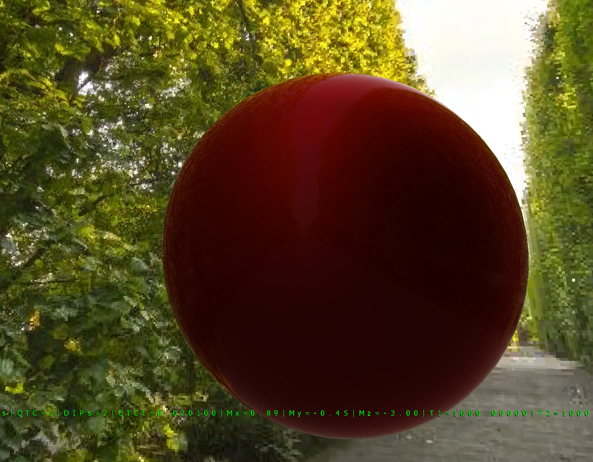
Well… Almost. Making this a red dielectric is not giving me the result I was expecting. My specular is not as bright as it should be. This brings me onto something that I've had an issue with for a while now and that's Fresnel. If you look at the F0 section on this page: https://academy.substance3d.com/courses/the-pbr-guide-part-1 you can see that the reflection of the environment is clearly visible in the red sphere all over it (possibly more reflective at grazing angles). I find it really hard to believe that the area at the centre of the sphere is only reflecting 4% of light (or whatever it is) and the edges are reflecting 100%. I am using 4% of light in my implementation and it does look like 4% of light, i.e. pretty dark - the point you can barely see the reflections apart from at grazing angles:
I'm sitting looking at my apple monitor which has shiny black bezels and looking directly perpendicular to it, I can definitely see more than 4% light being reflected. Past my head I can see the reflection of my back garden which is relatively bright.
float3 F0 = lerp(dielectric, albedo, metalness);  // dielectric is 0.04
float3 indirectSpecular = prefilteredColour * (F0 * envBRDF.x + envBRDF.y);  // prefilteredColour is my original non-changed environment map
The only way I can get mine to look similar to the substance3d one is to raise the F0 by a considerable amount (like by a factor of 10 or something). My irradiance map is not great at the moment, I've approximated it by heavily blurring my environment map but this doesn't contribute to the specular part. Have I missed a trick here? Is there a special grayscale specular map that I need to be including which increases this value? Or has Fresnel just got it all wrong :-) Obviously he hasn't, but have I misinterpreted what 4% reflected light means for dielectrics?
On another point, does anyone know of any decent free tools to create irradiance maps? I haven't got time at the moment to write my own.
You want to be careful when validating your renderer like this. Your eyes can be useful in determining if something is off, but they may not tell you what exactly the problem is. This is an issue I tend to have every once in a while when working with artists: they're good at point out that things don't look quite right, but they'll often propose fixes that aren't really addressing the true problem. So for something like this you want to be careful not to blame your fresnel or specular term when maybe diffuse is off! You also want to be careful directly comparing to photographic references, since in your case that environment map you're using may not have correct intensities (which is very common for environment maps, the real world has a very high dynamic range that can be difficult to capture correctly).
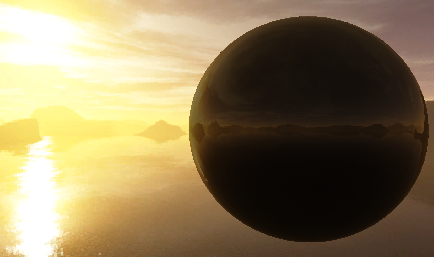
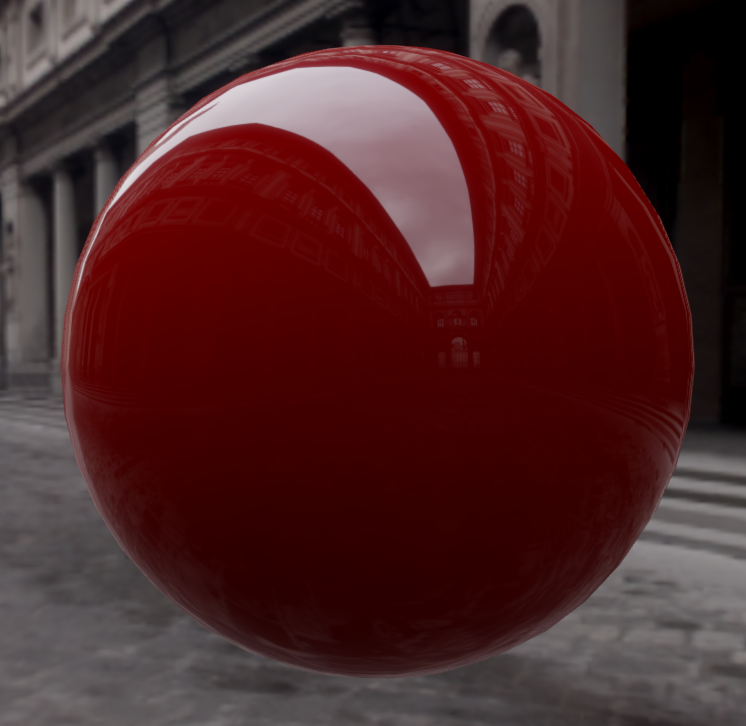
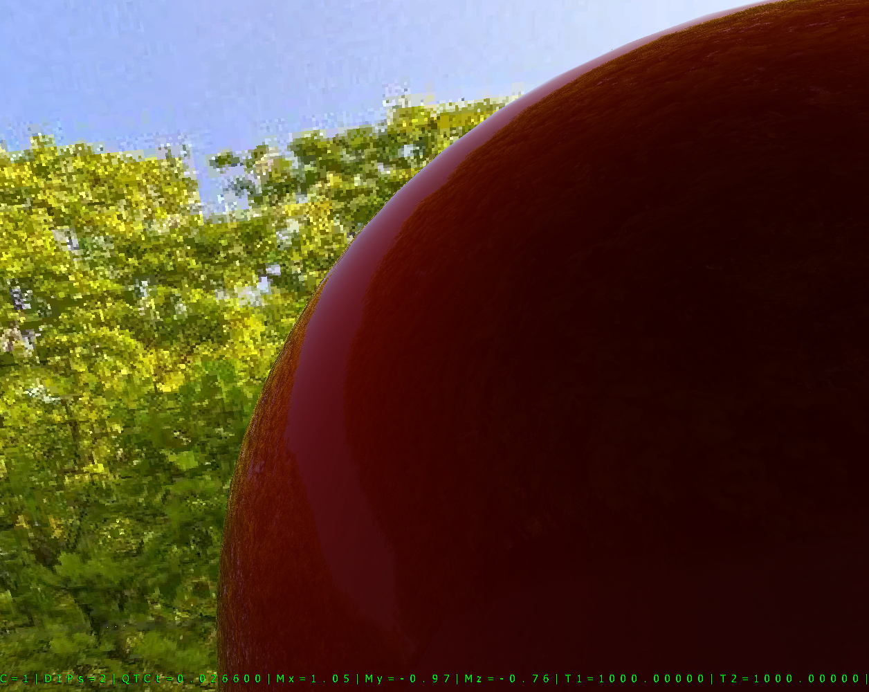
I think to start off you probably want to make sure that your diffuse term is correct. It's not entirely wrong to say that you can compute diffuse by “blurring” the radiance from an environment map, but you do need to make sure that it's the correct kernel (a cosine kernel in the case of lambertian diffuse). You also want to be careful that you're not losing or creating energy during the filtering step, otherwise the diffuse will have the wrong intensity. The diffuse intensity can have a huge effect on the perceived brightness of the specular reflections, since the human visual system is all based off of relative intensities. As an example, here's a non-metallic red sphere with an albedo of (1.0, 0.0, 0.0) with F0 of 4%:
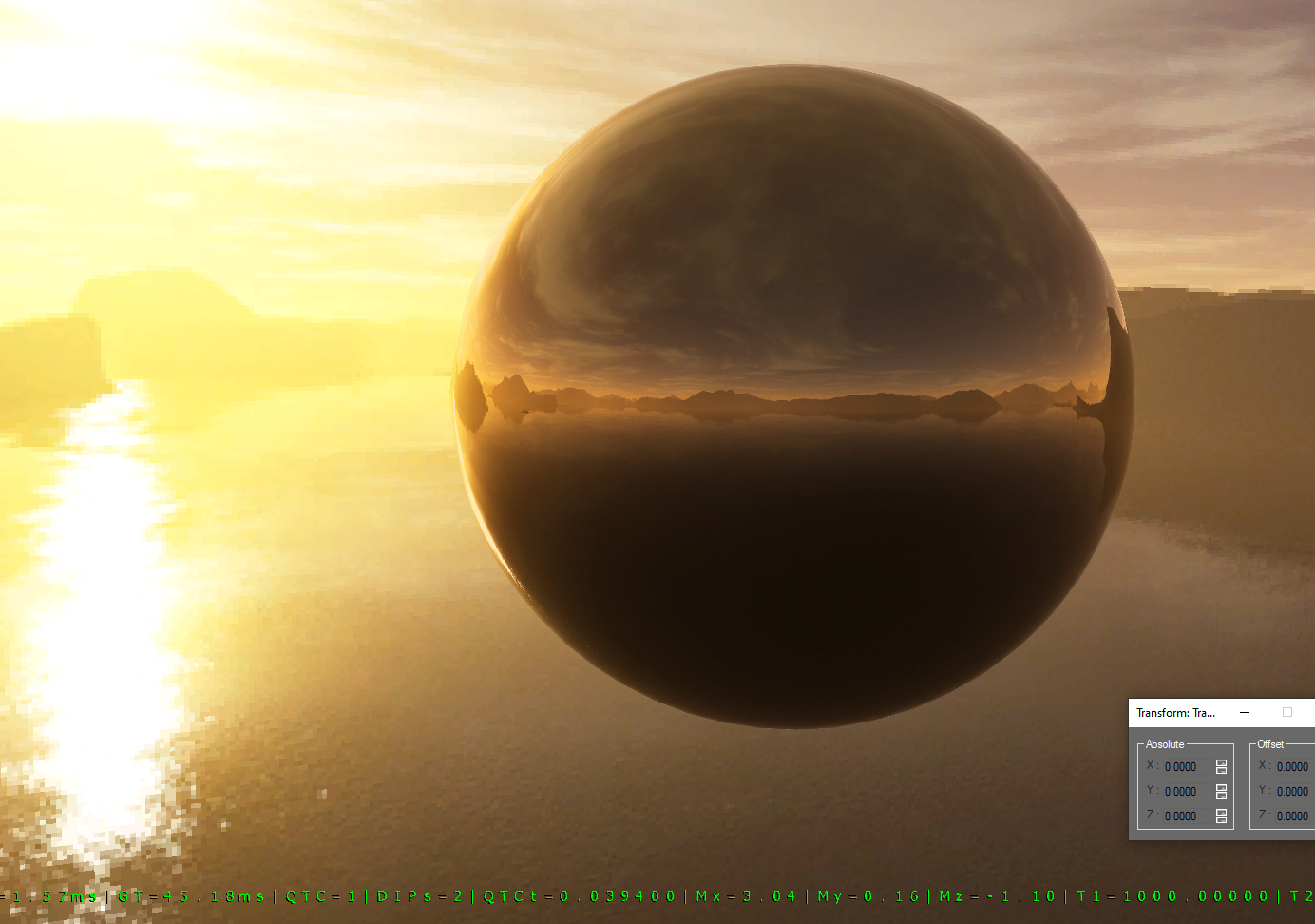
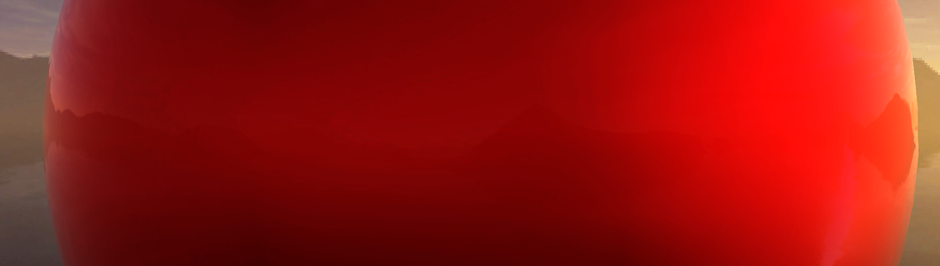
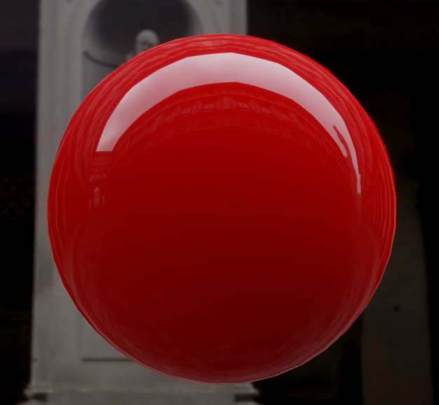
Now here's the same sphere with a darker red albedo of (0.5, 0.0, 0.0), which is about (0.2, 0.0, 0.0) when converting from sRGB to linear space:
The second sphere looks like it has brighter and clearer reflections, even though the specular stayed the same. I also think it looks more realistic, and this likely because an albedo of (1.0, 0.0, 0.0) isn't really physically plausible (it would be a very bright red). I would suspect this is what's happening when you're looking at your monitor bezel: the black color causes very little diffuse reflection, and the specular appears brighter in comparison.
In general I would say the shading model and environment map holds up reasonably well against a reference photo of a pure red surface that's not in direct sunlight:
If you suspect there's an issue in your own implementation, a good thing to do is to compare against a well-known reference renderer. I've used Mitsuba for this in the past, but a commercial renderer can work as well. Using a renderer can help for doing an apples-to-apples comparison, as long as you can give it the same lighting environment that you're using in your own renderer.
Thanks again MJP for your really helpful detailed posts, it's so great to see similar renderings that look right so I really appreciate your time. I understand everything you're saying but this is my specular calculation:
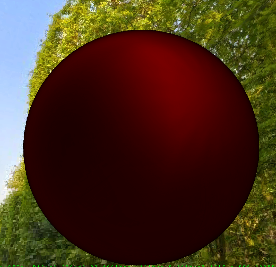
This gets added to my indirectDiffuse (which looks okay I think, with no specular - pic below) to produce the final colour. ‘prefilteredColour’ is just the original non-filtered/non-changed environment map. Thing is, if you look at your final image above, the sky highlight would not attract any bias (envBRDF.y) as it's not close enough to grazing angle and I'd imagine the scale (envBRDF.x) is close to 1.0 for full glossiness. If you look at my calculation, even if you had a prefilteredColour of white, it would never get above 0.04 unless you're getting toward grazing angles. I can see this in my example below (now using the env map and irradiance map from here: https://www.indiedb.com/features/using-image-based-lighting-ibl).
I can't really see how have a dielectric of 0.04 across the whole range of (non-biased) viewing angles will ever give a brighter specular highlight than around 0.04 as if everything is one, you'll still end up with 0.04. You seem to have a very distinct contrast between the brightness of the sky highlight and the roof. As you can see above, I'd expect the sky highlight in the middleish of the sphere and going up, to be far brighter. If I render with no specular (so just rendering the indirectDiffuse here), it does look a bit dark to me but I still think the issue is with the specular calc:
Grazing angles look relatively okay as the bias is brightening up the specular, but still not bright enough:
I spent some more time on this trying to work out why my specular didn't look right and I've just twigged that I was passing the wrong value into the envBRDF texture coordinate. v = 0 is shiny and v = 1 is rough, I had it the opposite way round, looks good now. Thanks again MJP and Joe