So I’m still experimenting with adding PBR to my engine. I came across split sum approximation recently which I think is great and I’d like to consider implementing something similar.
What I’m confused about is the second part of the split sum approximation, IBL specular and the pre-computed BRDF texture which is a 2 channel approximation texture for the specular highlight. In all implementations I’ve seen, two sample the BRDF texture, they use roughness (0-1) and n dot v (normal dot view vector). How does this approximate specular with a view to the position of the light in terms of the specular highlight? Surely you need to include the light position or vector?
RobMaddison said: How does this approximate specular with a view to the position of the light in terms of the specular highlight? Surely you need to include the light position or vector?
No. Because the reflectance behavior of a material dos not depend on it's environment (like lights) - only on the material itself.
In other words, you only want to calculate how to sample the environment - which regions contribute the most on what the eye sees as reflection. So you calculate a cone, or ray directions and densities, for example. But what then actually is visible in this cone (e.g. a light or just a dark wall) does not affect your calculation of this sampling distribution. So you do not need to know about lights at this point.
Hope this helps.
Thanks for the post but I’m still not clear here. Isn’t the second part of the split sum approximation supposed to add the specular highlight on top of the irradiance already added? In order to add a specular highlight surely you need to know the position of the light?
The reason it doesn't take the light direction into account is because that's the specific trade-off that was made for the split-sum approximation: it assumes that you can pre-integrate a few of the BRDF teams for a set of roughness + viewing angles, and then afterwards you can multiply it with the pre-filtered lighting environment. In reality this assumption is incorrect except for case where the entire lighting environment is a constant color, which is of course never the case. If you think about it it's actually the exact same assumption made by ambient occlusion, which also decouples the visibility from the lighting environment and multiplies them together after the fact.
Thanks for the explanations guys. I think I've got this wrong in my head. I tend to only be able to picture these types of things from a practical or code level as my maths isn't brilliant. From the code and my rough implementation, what I ended up with was not what I thought this BRDF part of the split sum approximation was meant to be and I kind of need to understand these things in real terms rather than mathematical.
So imagine you have a sphere. Coming at this from a coding perspective and in a pixel shader, if you dot the view angle with the normal at each pixel, you'll get a value of 1 at the centre of the sphere (as the normal will be perpendicular to the view angle, and you'll get a value of 0 at the sides of the sphere. That says to me that this pre-computed BRDF map gives you a value between 0 and 1 (ignoring bias for a second) based on the grazing angle of the sphere, nothing to do with the light direction (jmonkeyengine has a post on this where he does use light vector in his description, but view vector in the code confusingly…). So this means this can't have anything to do with the brightness of the specular highlight (a la phong) of the sphere. I think this is where I was getting confused, I assumed the BRDF map was a way of getting a more accurate specular reflection, but I guess you just get that from the environment map as the lights are baked into that anyway….?
So the second part of the split sum approximation (the pre-computed BRDF map) is used to enhance or brighten reflections at higher grazing angles, is that right? Kind of like fresnel?
RobMaddison said: but I guess you just get that from the environment map as the lights are baked into that anyway….?
Yeah that's what i tried to say. In IBL you have the whole environment available, including the lights. So that's very different from our common way to have point or spot lights. You can think of IBL as a light from everywhere but with variable intensity and color, and we sample from that along the reflection vector to get what we are actually interested in. I assumed your main confusion comes from missing the direction towards point / spotlights. But we don't need this in IBL because we can sample reflection direction directly and do not need to calculate how a light from somewhere in space affects this.
RobMaddison said: So the second part of the split sum approximation (the pre-computed BRDF map) is used to enhance or brighten reflections at higher grazing angles, is that right? Kind of like fresnel?
Having implemented PBR only for a raytracer with no support for environment image i'm unsure as well, and i have forgotten all the details i knew already. : ) So can't answer, but i would agree.
@undefined Thanks for explaining everything, that pre-computed BDRF map makes sense now. Final question though, for a metal material, for example copper, I’ve seen it written that you should treat the diffuse/albedo as black and then tint the specular that is multiplied by the environment map. This does indeed give a coppery look to my sphere, but because I’m multiplying by RGB values less than one, the light source in the environment map looks darker than it should be which looks unnatural to me. Seems I almost need to tint the reflection without losing any brightness from the near-to-1 areas in the environment map. Do I need to overlay some kind of specular highlight to enhance this?
So this is difficult to explain in terms of point lights, since point lights are hack that were invented to avoid having to do the expensive integrals that are involved with handling area or environment lighting sources. Let's start off by showing how you might compute environment lighting if we didn't care too much about performance:
float3 sampleSum = 0.0f;
for(uint sampleIdx = 0; sampleIdx < NumSamples; ++sampleIdx)
{
    float2 randomNumbers = RandomSampleNumbers(sampleIdx);

    // Pick a random microfacet normal, and reflect the view ray off of it
    float3 L = GGXSampleDir(V, N, roughness, randomNumbers);
    float sampleWeight = GGXSampleWeight(V, N, roughness, randomNumbers);
    float3 envLighting = SampleEnvLighting(L);
    sampleSum += ComputeGGXBRDF(L, V, N, roughness, specAlbedo) * envLighting * sampleWeight;
}

float3 specular = sampleSum * NumSamples;
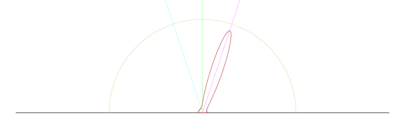
This is pretty standard monte-carlo integration with importance sampling. We're summing a bunch of random samples with the appropriate monte carlo weighting factors, and we're using a function (GGXSampleDir) to specifically importance sample a GGX specular BRDF to reduce the noise. The way that GGXSampleDir normally works is that you randomly pick one of the “microfacets” that you're simulating in a microfacet BRDF according to how likely it is for one of them to be present on the surface (less roughness means the microfacets are more uniform and more likely to point in the same direction as the surface normal, higher roughness means they're more varied and more likely to point in a different direction). Then you reflect the incoming view direction off that microfacet and you get a outgoing vector that you can treat as your “L” vector that you use in lighting equations. This is sort-of backwards from you do with a point light: with a point light there's just one direction that exists where the light is active, so you know you have to sample that direction. With an environment light there's lighting in every direction, so you either have to sample every possible direction or use importance sampling to mostly sample in directions where the BRDF gives you a non-zero result. That “set of directions where the BRDF is non-zero” is what you might call a “lobe” or “slice” of the BRDF. If you were to actually take a particular roughness + viewing angle, compute the value of ComputeGGXBRDF() for every possible outgoing L vector, and then graph the results, you'll get these funky lobe-looking things that like this:
Here the light blue line is the view direction, and the purple line is the view direction reflected off the normal (green line). Note how the lobe roughly lines up its peak with the reflection vector, which is typical of specular BRDFs.
Alright, so we know that the code I posted above is expensive because you have to take a whole lot of samples to get non-noisy results out of it. So if you want to do it on the cheap, you need to find a way to avoid doing that whole expensive integral at runtime. We know that the final specular result depends on the lighting environment (2D with spherical coordinates), the roughness, the view direction (also 2D), the RGB specular albedo (3D). This is too many parameters for pre-computing everything in a lookup texture, so instead we have to get creative. So what if we try to split things up into two different lookup textures: one that has a pre-filtered version of the environment lighting, and another that tries to encode the results of ComputeGGXBRDF? There's no way to do this and obtain the correct results, but perhaps it's good enough. And that's exactly what the split-sum approximation does here: it basically runs that loop I posted above for a set of roughnesses and viewing angles, assuming that SampleEnvLighting() returns 1.0. Then it combines that value with a (pre-filtered) environment cubemap at runtime to approximate the result.
There are still some details to work out though in terms of how to get everything to fit into a 2D lookup texure. We mentioned before that each BRDF lobe requires view direction + roughness + specular albedo which is 6 dimensions. How do we get that down to 2? First, we take advantage of the fact that the BRDF is isotropic. Basically this means that you could rotate that lobe graph I posted above around the normal (green line), and it would look exactly the same. This means that if we're going to pre-sum the values inside that lobe, we only need to care about the angle between the view direction and normal. That knocks us down from 6 values to 5, and it's the reason why you compute dot(N, V) to lookup into the texture. The other clever thing Brian did here was to re-formulate how the fresnel term works so that we can drop the specular albedo entirely. Basically he split the integral result into two values, where you can reconstruct the full lobe sum by doing specAlbedo * lookup.x + lookup.y. So that brings us down to 2 dimensions, and we can store in a 2D texture that lookup using cos(viewAngle) + roughness.
To answer your other questions: yes, the BRDF lookup texture will generally give you brighter results when viewing at grazing angles (dot(V, N) is close to 0). This is due to a combination of the Fresnel and geometry/visibility terms used in a microfacet BRDF, both of which cause the highlight to get more intense at grazing angles.
For a pure metal like copper it's true that the diffuse response should basically be 0. For your specular however you don't want to just “tint” the specular, you want use a proper specular albedo. Your specular albedo is usually known as the “F0” term, because it's the specular color you get when viewing at a head-on 0-degree angle (dot(V, N) == 1.0). You use this as an input to your fresnel term, which then causes the reflection to go to white at grazing angles. If you're doing pre-filtered environment lighting then you would do specAlbedo * lookupTexture.x + lookupTexture.y like I mentioned in my previous post. You should get something like this when doing that with a specAlbedo that's reddish-colored (I used (0.9, 0.53, 0.45):