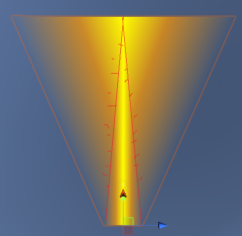
On picture 1 is actually what I get, but how to make it to look like pic 2?
I'd say start by showing how you made picture 1. Obviously something is wrong in the settings, but without you telling us what you did, we can't point out the error. In other words, show the core code for making picture 1.
For comparison with a simpler case, your question is like "The answer I got is 3. I want the answer to be 7. What did I do wrong?" No way to tell what is wrong without having the steps to obtain 3.
Ok sorry for bad explanation, I was in hurry...
The code for next image is[in unity]
 void CreateLaserWW(Vector3 beg, Vector3 end, float widthbeg, float widthend)
    {
        Vector3 dir = end - beg;
        Vector3 keydir = dir;
        keydir = Quaternion.AngleAxis(90.0f, Vector3.up) * keydir;
        keydir.Normalize();

        Vector3 begleft, begright, endleft, endright;
        begleft.y = beg.y;
        begleft.x = beg.x + (keydir.x * widthbeg);
        begleft.z = beg.z + (keydir.z * widthbeg);

        begright.y = beg.y;
        begright.x = beg.x - (keydir.x * widthbeg);
        begright.z = beg.z - (keydir.z * widthbeg);

        endleft.y = end.y;
        endleft.x = end.x + (keydir.x * widthend);
        endleft.z = end.z + (keydir.z * widthend);

        endright.y = end.y;
        endright.x = end.x - (keydir.x * widthend);
        endright.z = end.z - (keydir.z * widthend);


        keydir = begleft - beg;
        keydir = Quaternion.AngleAxis(-90.0f, dir.normalized) * keydir;


        keydir.Normalize();

        Vector3 begleft2, begright2, endleft2, endright2;
        begleft2.y = beg.y + (keydir.y * widthbeg);
        begleft2.x = beg.x + (keydir.x * widthbeg);
        begleft2.z = beg.z + (keydir.z * widthbeg);

        begright2.y = beg.y - (keydir.y * widthbeg);
        begright2.x = beg.x - (keydir.x * widthbeg);
        begright2.z = beg.z - (keydir.z * widthbeg);

        endleft2.y = end.y + (keydir.y * widthend);
        endleft2.x = end.x + (keydir.x * widthend);
        endleft2.z = end.z + (keydir.z * widthend);

        endright2.y = end.y - (keydir.y * widthend);
        endright2.x = end.x - (keydir.x * widthend);
        endright2.z = end.z - (keydir.z * widthend);

        MeshFilter mf = GetComponent<MeshFilter>();
        Mesh mesh = new Mesh();
        mf.mesh = mesh;

        Vector3 middle = beg + (dir * 0.5f);
        Vector3 beghalf = (begleft + begright) * 0.5f;

        Vector3[] vertices = new Vector3[9]
        {
            begleft,
            endleft,
            endright,
            begright,
            begleft2,
            endleft2,
            endright2,
            begright2,
            beghalf
        };

        int[] tri = new int[3 * 3];
        tri[0] = 0;
        tri[1] = 1;
        tri[2] = 8;

        tri[3] = 1;
        tri[4] = 2;
        tri[5] = 8;

        tri[6] = 2;
        tri[7] = 3;
        tri[8] = 8;

        Vector2[] uv = new Vector2[9];
        uv[1] = new Vector2(0, 0);
        uv[2] = new Vector2(0, 1.0f);
        uv[3] = new Vector2(1.0f, 1.0f);
        uv[0] = new Vector2(1.0f, 0);
        uv[8] = new Vector3(1.0f, 0.5f);

        mesh.vertices = vertices;
        mesh.triangles = tri;
        mesh.uv = uv;

    }
Code does:need width of bases of trapezoid and positions and renders it
Point of this code is to render a
As you can see this quad mesh is made of 3 triangles ,but texture is not evenly distributed on the quad(trapezoid),
with 2 triangles it's even worse,
There is similar post about this but in opengl The link
But how to make it in unity