Advertisement

Viewports required?

Started by September 30, 2017 12:28 PM
7 comments, last by noodleBowl 7 years, 4 months ago

I'm attempting to get a triangle to display in DirectX 11, but it seems like I can only get it to show when I have created and set a viewport

Is having at least 1 viewport set required in DirectX 11? If not what have I done wrong if my triangle's vertex data looks like:


Vertex vertices[] = {
  {0.0f, 0.0f, 0.0f, 1.0f, Color(1.0f, 0.0f, 0.0f, 1.0f)},
  {100.0f, 0.0f, 0.0f, 1.0f, Color(1.0f, 0.0f, 0.0f, 1.0f)},
  {100.0f, 100.0f, 0.0f, 1.0f, Color(1.0f, 0.0f, 0.0f, 1.0f)}
}


IIRC, D3D9 would automatically set the viewport to the full render-target size whenever you bind a render-target (so if you want a sub-viewport, you would have to remember to set it after you bind an RT) but D3D11 does not perform this same automatic function, so you have to always remember to set the viewport area manually.

Advertisement

When I do set the viewport it "transforms" the screen into a normalized state:


 0, 0 is center of screen
-1, 1 is top left
-1,-1 is bottom left
 1, 1 is top right
 1,-1 is bottom right

Does this also mean I have to divide my X and Y vertex positions by the viewport width and height? It there a way to have DirectX automatically do this?

Example I want to draw a quad that is 50x50. My viewport is 800x600. So to get the proper size


Width vertex value X:
50/800 = 0.0625

Height vertex value Y:
50/600 = 0.0833333333


How does the view port effect things like the MVP Matrix? Seems like it will throw everything off. That all of my positions have to be divided by the viewport width / height

Your vertex shader is expected to output vertices in "clip space", where X, Y are between -W and +W and Z is between 0 and +W, and everything outside of that range is clipped (see the section called "Viewport culling and clipping" in this article for more info, or google for "clip space" to find some more resources if you're curious).

cs-354-graphics-math-18-728.jpg

(note that this image is using OpenGL conventions where Z is between -W and +W, whereas D3D specifies that Z is between 0 and W)

The rasterizer expects homogeneous coordinates where the final coordinate will be divided by W after interpolation, which is how you get to the [-1, -1, 0] -> [1, 1, 1] "normalized device coordinate" space that you're referring to in your above post.

So with the details out of the way, let's say that we wanted to position a triangle so that it has one vertex at the top-middle of the screen, on one the right-middle of the screen, and one in the very center of the screen: 

Example_Triangle.png.7bb5c1a5de4ad2386916abc9ec5ee421.png

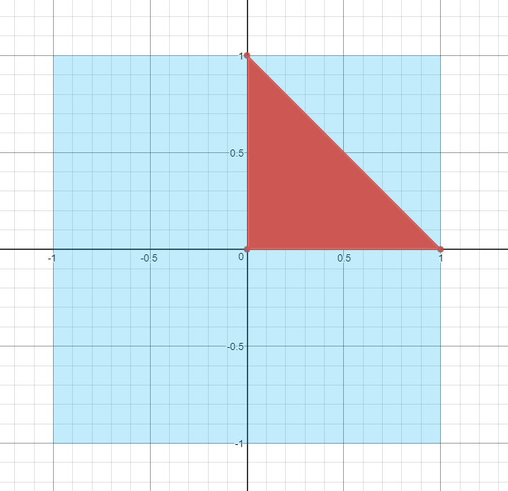
The easiest way to do this is to use a value of 1.0 for W, which means we can specify the XYZ coordinates in NCD [-1, -1, 0] -> [1, 1, 1] space. So to get the triangle where we want, we could set the three vertices to (0, 1, 1, 1), (1, 0, 1, 1), (0, 0, 1, 1). If we do this, the triangle will be rasterized in the top-right quadrant of the screen, with all pixels having a z-buffer value of 1.0. 

In practice, you usually don't calculate vertex coordinates in this way except in special circumstances (like drawing a full-screen quad). Instead you'll apply a projection matrix that takes us from camera-relative 3D space to a projected 2D space, where the resulting coordinates are perfectly set up to be in the clip space that I mentioned earlier. Projection matrices typically aren't too fancy: they're usually just a scale and a translation for X, Y, and Z, with either 1 or Z ending up in the W component. For 2D stuff like sprites, orthographic matrices are usually the weapon of choice. For X and Y, an orthographic matrix will usually divide X and Y by the "width" and "height" of the projection, and possibly also shift them down afterwards with a translation. If you think about it, this is a perfect way to automatically account for the viewport transform so that you can work in 2D coordinates. Let's say you wanted to work such that (0, 0) is the bottom left of the screen, and (ViewportWidth, ViewportHeight) is the top. To go from this coordinate space to [-1, 1] NCD space, you would do something like this:


// Go from [0, VPSize] to [0, 1]
float2 posNCD = posVP / float2(VPWidth, VPHeight);
// Go from [0, 1] to [0, -1]
posNCD = posNCD * 2.0f - 1.0f;

Now you can do this yourself in the vertex shader if you'd like, but if you carefully look at how an orthographic projection is set up you should see that you can use such a matrix to represent the transforms that I described above. You can even work an extra -1 into the Y component if you wanted to have your original coordinate space set up so that (0, 0) is the top-left corner of the screen, which is typical for 2D and UI coordinate systems.

Perspective projections are a little more complicated, and aren't really set up for 2D operations. Instead they create perspective effects by scaling X and Y according to Z, so that things appear smaller as they get further from the camera. But your typical symmetrical perspective projection is still doing roughly the same thing as an orthographic projection, in that it's applying a scale and translation so that your coordinates will end up with (-W, -W) as the bottom left of the screen and (W, W) as the top right. One of the major difference is that an orthographic projection will typically always set W to 1.0, while a perspective projection will typically set it the Z value of the coordinate before the projection was applied. Then when homogeneous "divide-by-w" happens, coordinates with a higher Z value will end up being closer to 0, which makes geometry appear smaller as it gets further away from the camera.

@MJP

Thanks for this info! I knew a projection matrix was needed and that it would set up how the "camera" acts, but I didn't realize it would transform everything into that NDC [-1,1] space

One thing I'm still very confused about is when calculating the MVP matrix what is the order the matrix multiplication supposed to be done in?


I currently have a Matrix4 class which is really just a float[16] array, where the matrix itself is based on column major order. My MVP matrix is calculated on the CPU side and when I do the following:


//Vertices being used to draw a triangle
Vertex vertices[] =
{
  { 0.0f, 0.0f, 1.0f, Color(1.0f, 0.0f, 0.0f, 1.0f) },
  { 0.0f, 100.0f, 1.0f, Color(1.0f, 0.0f, 0.0f, 1.0f) },
  { 100.0f, 100.0f, 1.0f, Color(1.0f, 0.0f, 0.0f, 1.0f) }
};

/*Other setup stuff*/

//Setup the matrices
Matrix4 model; //Setup as identity by default
Matrix4 view;
Matrix4 projection;
projection.setAsOrthographic(800.0f, 600.0f, 0.0f, 1.0f);
view.moveX(100.0f);

Matrix4 mvp = projection * view * model;

My MVP seems to be working in the sense that the moveX call will use "screen coords" space and move by triangle by 100 pixels. Where as if I do the same but change the order of the MVP calculation to:


Matrix4 mvp = model * view * projection;

The call to moveX needs to use the NCD [-1,1] cord space. Actually saying moveX(1.0f) displays nothing to the screen where as moveX(-1.0f) displays the triangle on the left edge of the screen

Should this ordering even matter? I feel like the projection * view * model ordering is wrong. In tutorials I have read where they calculate the MVP in the shader they have the model * view * projection ordering


//Vertex Shader code from tutorials I have read
PixelInputType ColorVertexShader(VertexInputType input)
{
    PixelInputType output;

    // Change the position vector to be 4 units for proper matrix calculations.
    input.position.w = 1.0f;

    // Calculate the position of the vertex against the world, view, and projection matrices.
    output.position = mul(input.position, worldMatrix);
    output.position = mul(output.position, viewMatrix);
    output.position = mul(output.position, projectionMatrix);
    
    // Store the input color for the pixel shader to use.
    output.color = input.color;
    
    return output;
}

//For comparison, my vertex shader code
VOut VShader(float3 position : POSITION, float4 color : COLOR)
{
	VOut output;
	output.position = mul(mvp, float4(position, 1.0f));
	output.color = color;

	return output;
}


6 hours ago, noodleBowl said:

I currently have a Matrix4 class which is really just a float[16] array, where the matrix itself is based on column major order.

There's two choices here.
(1) Do you store your array in row-major or column-major order. This is just a computer science 2D array problem that only affects internal implementation details.
(2) Do you write your basis vectors as columns or rows in the matrix. This choice actually changes how you would write the math down on paper and decides what order you do your matrix multiplication in.

If you write your basis vectors in the columns of a matrix, then some more explicit names for your three matrix variables might be: world_from_model, view_from_world, and projection_from_view.
You can then calculate:


projection_from_model = projection_from_view * view_from_world * world_from_model
//and transform vertices like:
projected_vertex = mul( projection_from_model, model_vertex )

On the other hand, if you choose to write your basis vectors in the rows of a matrix, then more explicit matrix names might be: model_to_world, world_to_view, and view_to_projection.
And you concatenate matrices like:


model_to_projection = model_to_world * world_to_view * view_to_projection
//and transform vertices like:
projected_vertex = mul( model_vertex, model_to_projection )


As for (1), HLSL uses column-major array storage by default, so if you choose to use row-major array indexing in your matrix implementation, then you need to use the keyword "row_major float4x4" to declare a matrix variable in your cbuffers, or, you should transpose your matrices on the CPU side before sending them to HLSL.

Lots of D3D tutorials will use row-major array indexing and row vectors in their math, because this is what D3DX, DirectXMath and earlier DirectX fixed function math chose.
Lots of GL tutorials will use column-major array indexing and column vectors in their math because that's traditionally the conventions that GL has used.

But you're free to use any set of conventions on any API. Both GL and D3D work equally well with row-vector/column-vector matrices and row-major/column-major arrays.

AFAIK, column-vector math is more popular in general (although I'm sure there's a mathematician reading who was raised on row-vectors), and row-vector math only became common within the computer graphics community because early computer graphics researchers had to type up their papers on typewriters, and row-vector math is easier to write on a typewriter, so they would convert all their math to that format prior to publishing!

Advertisement
1 hour ago, Hodgman said:

AFAIK, column-vector math is more popular in general (although I'm sure there's a mathematician reading who was raised on row-vectors), and row-vector math only became common within the computer graphics community because early computer graphics researchers had to type up their papers on typewriters, and row-vector math is easier to write on a typewriter, so they would convert all their math to that format prior to publishing!

There's also the fact that most graphics software were originally developed using Fortran, which uses column-major order for its built-in matrix type.  It's much much easier to write matrix software in row-major order in C and derivative languages because all the data in a row is physically adjacent in memory (the address of a component vector in matrix[a] is just matrix[a]), so current generations of developers are more used to that approach because who writes Fortran any more?

Stephen M. Webb
Professional Free Software Developer

17 hours ago, Hodgman said:

Do you write your basis vectors as columns or rows in the matrix

I assume since I have a column major based matrix my position vectors are also column based. Which would make sense why using model_to_projection = model_to_world * world_to_view * view_to_projection works, where as the other way does not

Lots of questions about the projection, view, model matrices then

Does this mean that for my view / model matrix that when I do a rotation, scale, or translation that it has a "correct" order too. Does this mean that my model/view matrix should really break down into 3 separate matrix each, otherwise I would have to keep track of when I would do a translation, scale, or rotation so I don't break the correct order?


Matrix4 model = translationMatrix * rotationMatrix * scaleMatrix;
//Same would be done for the view matrix

When rotating models is this correct?


Positive rotation
Rotation X: Turns the object towards the camera
Rotation Y: Spins the object around its center towards the right
Rotation Z: Turns the object clockwise

Negative rotation
Rotation X: Turns the object away from the camera
Rotation Y: Spins the object around its center towards the left
Rotation Z: Turns the object counter clockwise

When it comes to a perspective matrix, what is the different between D3DXMatrixPerspectiveLH vs D3DXMatrixPerspectiveFovLH?

Does the D3DXMatrixPerspectiveFovLH just allow you to change the FoV from the default? Does the D3DXMatrixPerspectiveLH not have a Fov?

Would there be any reason as to why my screen is blank when trying to use a perspective matrix (regardless if it is the FOV version or not), where as an orthographic matrix displays correctly? Maybe I'm not understanding the use of the Z position or its that I have not set up a depth buffer (although I would think objects would just draw on top of each other and ignore depth)


//Vertices for the tringle I'm drawing
Vertex vertices[] =
{
	{ 0.0f, 0.0f, 1.0f, Color(1.0f, 0.0f, 0.0f, 1.0f) },
	{ 0.0f, 100.0f, 1.0f, Color(1.0f, 0.0f, 0.0f, 1.0f) },
	{ 100.0f, 100.0f, 1.0f, Color(1.0f, 0.0f, 0.0f, 1.0f) }
};

//Displays nothing to screen
Matrix4 model;
Matrix4 view;
Matrix4 projection;
projection.makePerspectiveProjection(800.0f, 600.0f, 0.0f, 1.0f);
Matrix4 mvp = projection * view * model;

//Displays nothing to screen
Matrix4 model;
Matrix4 view;
Matrix4 projection;
projection.makePerspectiveProjectionFOV(45.0f, 800.0f/600.0f, 0.0f, 1.0f);
Matrix4 mvp = projection * view * model;

//Triangle displays to screen
Matrix4 model;
Matrix4 view;
Matrix4 projection;
projection.makeOrthographicProjection(800.0f, 600.0f, 0.0f, 1.0f);
Matrix4 mvp = projection * view * model;

//Vertex shader has this for position calculatlation transform
output.position = mul(mvp, float4(position, 1.0f));

Those microsoft matrices (D3DXMatrixPerspectiveLHD3DXMatrixPerspectiveFovLH, etc) formulas they have on those pages should I be transposing those since my matrix are in column major order?

This topic is closed to new replies.

Advertisement