Hi!
I'm posting here in the hope that someone can nudge me in the right direction with regards to tesselation shaders and quad patch rendering. (With regards to the setup and API usage.)
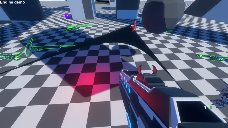
I'm currently attempting rendering a tesselated quad (4 vertices in the vertex buffer and 4 indices in the index buffer) the issue is that the setup/configuration of the renderpass and/or draw commands seems to cause incorrect rendering (the quad is only rendered partially if at all.)
That's how it currently looks like (the black triangle in the middle of the screen):

The setup to enable quad rendering is as follows:
I enabled the “VkPipelineTessellationStateCreateInfo" struct with a patch control size of 4:
VkPipelineTessellationStateCreateInfo tesselationStateCreateInfo;
tesselationStateCreateInfo.sType = VK_STRUCTURE_TYPE_PIPELINE_TESSELLATION_STATE_CREATE_INFO;
tesselationStateCreateInfo.patchControlPoints = 4;
tesselationStateCreateInfo.pNext = NULL;
tesselationStateCreateInfo.flags = 0;
Vertex Input is also set to patch list:
VkPipelineInputAssemblyStateCreateInfo inputAssembly = {};
inputAssembly.topology = VK_PRIMITIVE_TOPOLOGY_PATCH_LIST;
inputAssembly.primitiveRestartEnable = VK_FALSE;
This can be skipped but for completions sake here is the code to generate the plane:
unsigned int toLinearIndex(unsigned int arrayAxisSize, unsigned int x, unsigned int y)
{
	return (y * arrayAxisSize) + x;
}

Game::GameResources::WaterMeshData generateWaterMesh(Engine::Graphics::RenderFrontend* renderFrontend, Engine::Graphics::ObjectHandle::ReCommandPool commandPool, float size, unsigned int axisSubdivide)
{

	float stepSize = size / static_cast<float>(axisSubdivide);

	std::vector<glm::vec3> positionBuffer;
	std::vector<glm::vec2> uvBuffer;
	std::vector<std::uint32_t> indexBuffer;

	float floorRepeat = 0.01f;

	float offset = 0;//-size / 2.0f;


	//vertex & uv buffer
	for (unsigned int y = 0; y <= axisSubdivide; y++)
	{
		for (unsigned int x = 0; x <= axisSubdivide; x++)
		{
			positionBuffer.push_back(glm::vec3(static_cast<float>(x) * stepSize + offset, static_cast<float>(y) * stepSize + offset, 0.0f));
			uvBuffer.push_back(glm::vec2(floorRepeat * stepSize * static_cast<float>(x), static_cast<float>(y) * stepSize * floorRepeat));
		}
	}

	//index buffer
	for (unsigned int y = 0; y < axisSubdivide; y++)
	{
		for (unsigned int x = 0; x < axisSubdivide; x++)
		{
			indexBuffer.push_back(toLinearIndex(axisSubdivide, x, y));
			indexBuffer.push_back(toLinearIndex(axisSubdivide, x, y + 1));
			indexBuffer.push_back(toLinearIndex(axisSubdivide, x + 1, y));
			indexBuffer.push_back(toLinearIndex(axisSubdivide, x + 1, y + 1));
		}
	}

	Engine::Graphics::ObjectHandle::ReBuffer vbPosition;
	{
		VkDeviceSize bufferSize = sizeof(positionBuffer[0]) * positionBuffer.size();
		vbPosition = Engine::Graphics::RessourceBuilder::createVertexBuffer(renderFrontend, commandPool, (void*)positionBuffer.data(), bufferSize _DTRACK);
	}
	Engine::Graphics::ObjectHandle::ReBuffer vbUv;
	{
		VkDeviceSize bufferSize = sizeof(uvBuffer[0]) * uvBuffer.size();
		vbUv = Engine::Graphics::RessourceBuilder::createVertexBuffer(renderFrontend, commandPool, (void*)uvBuffer.data(), bufferSize _DTRACK);
	}

	Engine::Graphics::ObjectHandle::ReBuffer vbIndex;
	{
		VkDeviceSize bufferSize = sizeof(indexBuffer[0]) * indexBuffer.size();
		vbIndex = Engine::Graphics::RessourceBuilder::createIndexBuffer(renderFrontend, commandPool, (void*)indexBuffer.data(), bufferSize _DTRACK);
	}

	Game::GameResources::WaterMeshData waterMeshData;
	waterMeshData.vbIndex = vbIndex;
	waterMeshData.vbUv = vbUv;
	waterMeshData.vbPosition = vbPosition;
	waterMeshData.indexCount = indexBuffer.size();

	return waterMeshData;
}
whereas we only create a plane with 4 control points:
generateWaterMesh(renderer, commandPool, 10.0f, 1);//size 10 with 1 subdivision (4 vertices)in the command buffer we bind the vertex/index buffer and draw it
//bind
vkCmdBindVertexBuffers(commandBuffer, 0, vertexBuffers.size(), vertexBuffers.data(), 0);//bind vertex buffers which are contained in an std::vector
vkCmdBindIndexBuffer(commandBuffer, indexBuffer, 0, VK_INDEX_TYPE_UINT32);//bind index buffer


//draw
vkCmdDrawIndexed(commandBuffer, static_cast<uint32_t>(indexCount), 1, 0, 0, 0);
the shaders are fairly straightforward:
control shader:
#version 450

layout (vertices = 4) out;
layout (location = 0) out vec2 outUV[4];

layout(binding = 8) uniform TesselationUniform {
	mat4 modelView;
    int minTessLevel;
    int maxTessLevel;
    float minTessDistance;
	float maxTessDistance;
} ubo;


void main()
{
    if (gl_InvocationID == 0)
    {
		gl_TessLevelOuter[0] = 16;
        gl_TessLevelOuter[1] = 16;
        gl_TessLevelOuter[2] = 16;
        gl_TessLevelOuter[3] = 16;

        gl_TessLevelInner[0] = 16;
        gl_TessLevelInner[1] = 16;
    }

    gl_out[gl_InvocationID].gl_Position = gl_in[gl_InvocationID].gl_Position;
	outUV[gl_InvocationID] = vec2(0.0,0.0);
evaluation shader (notice that i set the layout to “quads”:
#version 450
#include "OceanWave.glsl"

invariant gl_Position;

layout (quads, fractional_odd_spacing, ccw) in;

layout(binding = 0) uniform UniformBufferObject {
    mat4 modelView;
    mat4 proj;
	mat4 transpInvModel;
	vec4 color;
	vec2 waveDirection;
	float waveSteepness;
	float wavelength;
} ubo;

layout (location = 0) in vec2 inUV[];


layout (location = 0) out vec2 outUV;
layout (location = 1) out vec3 vWorldPos;

void main()
{
	// get patch coordinate
    float u = gl_TessCoord.x;
    float v = gl_TessCoord.y;

    // ----------------------------------------------------------------------
    // retrieve control point position coordinates
    vec4 p00 = gl_in[0].gl_Position;
    vec4 p01 = gl_in[1].gl_Position;
    vec4 p10 = gl_in[2].gl_Position;
    vec4 p11 = gl_in[3].gl_Position;

    // compute patch surface normal
    vec4 uVec = p01 - p00;
    vec4 vVec = p10 - p00;
    vec4 normal = normalize( vec4(cross(vVec.xyz, uVec.xyz), 0) );

    // bilinearly interpolate position coordinate across patch
    vec4 p0 = (p01 - p00) * u + p00;
    vec4 p1 = (p11 - p10) * u + p10;
    vec4 p = (p1 - p0) * v + p0;

    // ----------------------------------------------------------------------
    // output patch point position in clip space
	gl_Position = ubo.proj * ubo.modelView * vec4(p.xyz, 1.0);
	outUV = vec2(0.0,0.0);


}
Is there something else i have to take into account compared to the usage of regular triangle based rendering? (did i miss something in the setup that has to be done for tesselation shader rendering?)
I also tried subdividing the geometry with 4 patches (basically rendering 4 quads with 4 control points each)
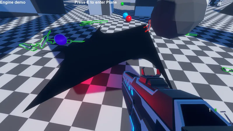
generateWaterMesh(renderer, commandPool, 10.0f, 2);//size 10 with 2 subdivision (4 quads with 4 vertices each)And the result looks like this:

It looks like either the index order is incorrect or it mixes the indices of the index buffer as well as not utilizing all data from the vertex buffers.
Can anyone point me in the right direction as to what might be wrong here?
/EDIT: Found the issue
In case anyone stumbles upon this in the future: The order of the indices in the patches matters!
While a lot of tesselation shader tutorials describe patches as points which define a hull without direct connectivity between the coordinates (as this isn't a trianglelist and you can also have more than 3 or 4 points per patch) the shader still has to generate triangles on the given patch in the shader.
And this happens in the evaluation shader here:
    // retrieve control point position coordinates NOTE: The order matters!
    vec4 p00 = gl_in[0].gl_Position;
    vec4 p01 = gl_in[1].gl_Position;
    vec4 p10 = gl_in[2].gl_Position;
    vec4 p11 = gl_in[3].gl_Position;

    // compute patch surface normal
    vec4 uVec = p01 - p00;
    vec4 vVec = p10 - p00;
    vec4 normal = normalize( vec4(cross(vVec.xyz, uVec.xyz), 0) );

    // bilinearly interpolate position coordinate across patch
    vec4 p0 = (p01 - p00) * u + p00;
    vec4 p1 = (p11 - p10) * u + p10;
    vec4 p = (p1 - p0) * v + p0;
you access the patch coordinates in the given order you loaded it in the memory which is then used to calculate the final coordinate of a vertex for the generated triangle.
So in case you get similar errors as on the screenshots above, either play around with the vertex order in the evaluation shader ( glin[x].gl_Position ) or rearrange the content of your vertex buffer/indexbuffer until your quad gets rendered correctly. (Which in hinsight makes sense. Don't assume that the tesselation shader automatically somehow figures out in which order the points have to be connected to generate an even tesselation accross its surface.)


