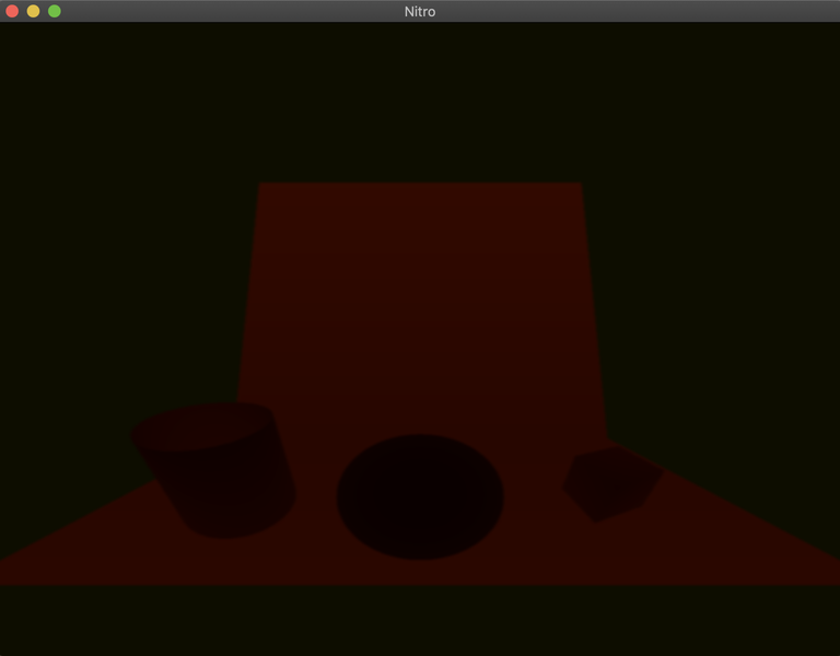
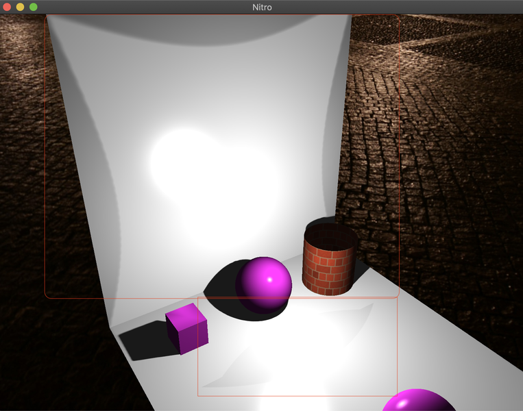
Hi guys, I'm doing a custom 3D renderer using OpenGL and C++ and right now I'm implementing shadows. For instance, my first attempt of implementing shadows was common shadow mapping with PCF but applying PCF to a cube texture map generates some artifacts and I was looking to some alternatives. Because of this, I stumbled upon Dual Paraboloid environment mapping and read that it could be used with variance shadow mapping since it generates two textures each covering a 180 degree spectrum. So, after reading a lot I implemented the algorithm but there are some artifacts that shouldn't be there:
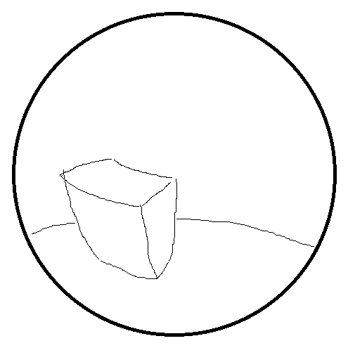
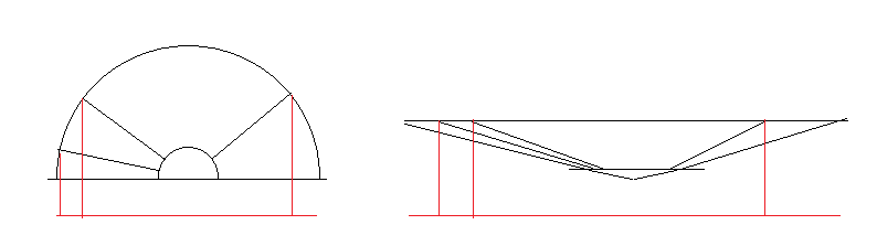
Now, after reading this paper http://www.klayge.org/material/3_12/DPSM/DPSM.PDF I found out that the artifact on the floor could be because of the orientation of the splitting plane and a solution would be to change the orientation from z (0,0,1) (0,0,-1) to maybe y (0,1,0) and (0,-1,0) but this would definitely change a lot of things from the original algorithm.
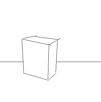
Also, the other artifact found is the one on the wall and I just don't know why it is happening, maybe it's because I'm not generating correctly the shadow maps or something.
The Vertex and Fragment shader for generating the shadow maps are the following: (I now that the algorithm produces better results when tessellation is used but the improvements are on the borders, right?)
// Vertex Shader
#version 410 core

in vec3 aPosition;

out VS_OUT
{
    float Depht;
    float Alpha;
} vs_out;

uniform mat4  uModel; // Model transform

/*

View transform which is implemented as follows:

LookAt(position_, position_ + clutch::Vec4<float>{0.0f, 0.0f, 1.0, 0.0f}, clutch::Vec4<float>{0.0f, 1.0f, 0.0f, 0.0f})

*/
uniform mat4  uView;

uniform float uFar;  // far plane
uniform float uNear; // near plaine
uniform float uDir;  // 1 if rendering the front side and -1 if rendering the rear one.

void main()
{
    vec4 result = uView * uModel * vec4(aPosition, 1.0);

    result.z *= uDir;

    result /= result.w;

    float len = length(result.xyz);
    result   /= len;

    vs_out.Alpha = 0.5 + (result.z / uFar);

    result.z += 1.0;

    result.x /= result.z;
    result.y /= result.z;

    result.z = (len - uNear) / (uFar - uNear);

    result.w = 1.0;

    vs_out.Depht = result.z;

    gl_Position = result;
}

// Fragment Shader

#version 410 core

out vec4 FragColor;

in VS_OUT
{
    float Depht;
    float Alpha;
} fs_in;

void main()
{
    if(fs_in.Alpha < 0.5) discard;

    FragColor = vec4(fs_in.Depht, fs_in.Depht * fs_in.Depht, 0.0, 0.0);
}
Before showing the results of the previous shaders it's important to point out that the before mentioned paper says that moving the Dual Paraboloid calculation to the fragment shader slightly solves the non linearity problem, but after doing so the same artifacts where encountered.
Now, the shadow calculations where implemented as follows:
float line_step(float min, float max, float value)
{
return clamp((value - min) / (max - min), 0.0, 1.0);
}
float reduce_bleeding(float p_max, float amount)
{
// Remove the [0, Amount] tail and linearly rescale (Amount, 1].
return line_step(amount, 1, p_max);
}
vec4 paraboloid(vec4 frag_pos, float dir)
{
vec4 result = frag_pos;
result /= result.w;
float len = length(result.xyz);
result /= len;
result.z = (result.z >= 0.0) ? (1.0 + result.z) : (1.0 - result.z);
result.x /= result.z;
result.y /= result.z;
result.z = (len - uNearPlane) / (uMaxDistance - uNearPlane);
result.w = 1.0;
return result;
}
float VSM(vec2 moments, float depht)
{
float m1 = moments.x;
float m2 = moments.y;
float variance = m2 - m1 * m1;
float diff = depht - m1;
float p_max = variance / (variance + diff * diff);
return depht < moments.x ? 1.0 : reduce_bleeding(p_max, 0.4);
}
float shadows(vec4 frag_pos)
{
frag_pos = uDPView * frag_pos; // Fragpos is in world space.
float alpha = 0.5 + frag_pos.z / uMaxDistance;
vec4 front_pos = paraboloid(frag_pos, 1.0);
vec4 rear_pos = paraboloid(frag_pos,-1.0);
vec2 front_coods = 0.5 + 0.5 * front_pos.xy;
vec2 rear_coods = 0.5 + 0.5 * rear_pos.xy;
vec2 moments = (alpha >= 0.5) ? texture(shadow_map_front, front_coods).rg : texture(shadow_map_rear, rear_coods).rg;
float depht = (alpha >= 0.5) ? front_pos.z : rear_pos.z;
return VSM(moments, depht);
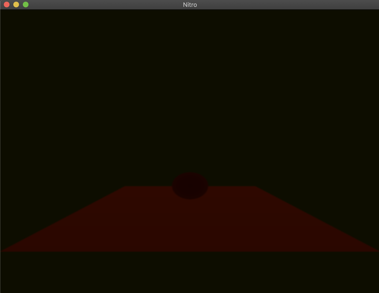
}Finally, the resulting shadow maps used for calculating the shadows are the following: