Advertisement

Contour of the shadow region

Started by June 15, 2018 12:35 PM
7 comments, last by matt77hias 6 years, 7 months ago

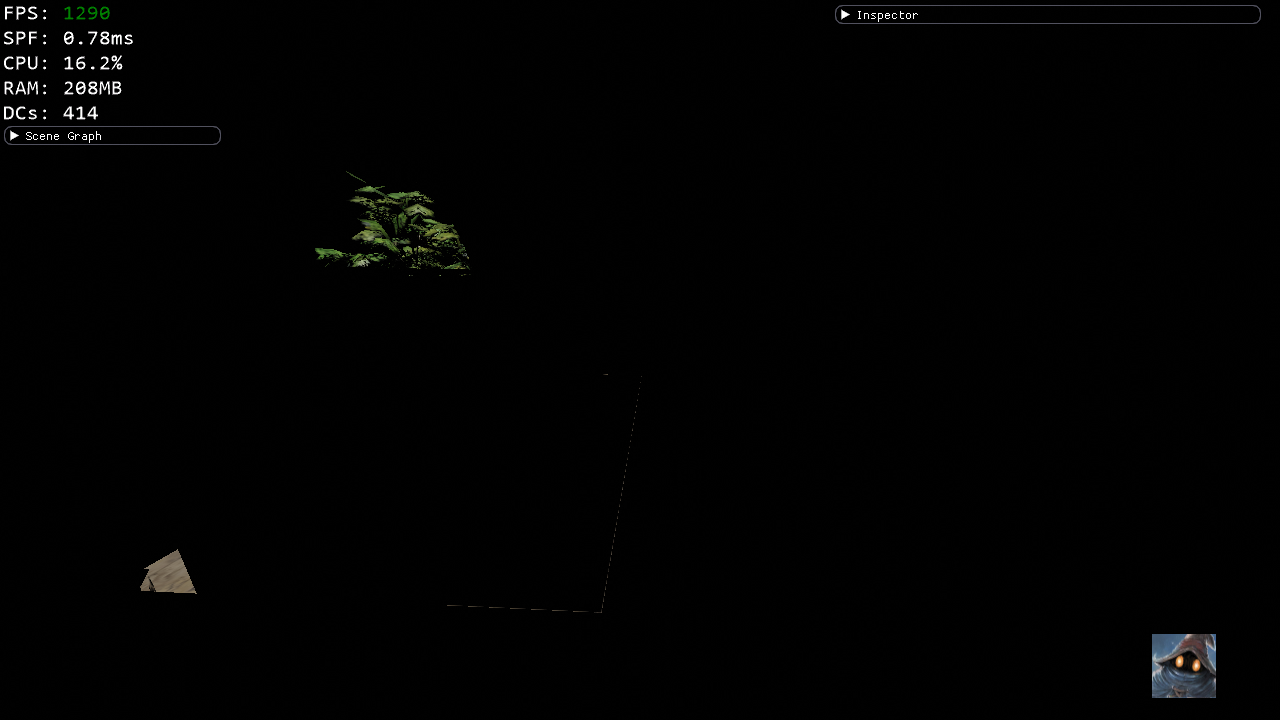
While adding shadows maps for directional light sources (spatially restricted to an AABB), I noticed a weird artifact at the border of the shadow map. The region to the right is not illuminated directly by the directional light source. Though, one can clearly see the contours of the orthographic projection plane projected onto the floor of the scene. (P.S.: blame GameDev.net for the image compression artifacts ;) )

screenshot-2018-06-15-13-50-14.thumb.png.f336b9f208a2d4a7860f90e3f835bb34.png

This contour corresponds to normalized texture coordinates outside the [0,1]^2 range (i.e. just outside the orthographic projection plane projected onto the floor of the scene). Since, I use a D3D11_TEXTURE_ADDRESS_BORDER, the PCF sampler state, will use the border color. This border color is equal to my far plane, so obviously the points will never lie inside a shadow.

By using a different border color, I can circumvent the problem:


#ifdef DISABLE_INVERTED_Z_BUFFER
desc.ComparisonFunc = D3D11_COMPARISON_LESS_EQUAL;
#else  // DISABLE_INVERTED_Z_BUFFER
desc.ComparisonFunc = D3D11_COMPARISON_GREATER_EQUAL;
desc.BorderColor[0] = 1.0f; // near instead of far plane = never in shadow
desc.BorderColor[1] = 1.0f; // near instead of far plane = never in shadow
desc.BorderColor[2] = 1.0f; // near instead of far plane = never in shadow
desc.BorderColor[3] = 1.0f; // near instead of far plane = never in shadow
#endif // DISABLE_INVERTED_Z_BUFFER

Unfortunately, this does not solve but rather hides the problem. The incident orthogonal irradiance of the directional light, should be zero. And since the contribution is zero, the shadow factor should not matter (i.e. it does not matter whether outside the shadow map region, points are considered lying inside or outside the shadow).

The incident orthogonal irradiance of the directional light is computed as follows:


void Contribution(DirectionalLight light, float3 p, out float3 l, out float3 E, out float3 p_ndc) {
    const float4 p_proj = mul(float4(p, 1.0f), light.world_to_projection);
    p_ndc = HomogeneousDivide(p_proj);
    
    l = light.neg_d;
    E = (any(1.0f < abs(p_ndc)) || 0.0f > p_ndc.z) ? 0.0f : light.E; // Should be zero outside the shadow map region.
}

The position, p_ndc, expressed in Normalized Device Coordinates is transformed to UV coordinates ([-1,1]x[-1,1]x[0,1] maps to [0,1]x[1,0]). The latter will be used in HLSL's SampleCmpLevelZero.

But am I allowed to use p_ndc as computed above directly? Do I miss a half-texel offset?


Edit: Given that "(any(1.0f < abs(p_ndc)) || 0.0f > p_ndc.z)" is false, the point should be located inside the AABB and thus inside the shadow map region. But in this case, how is it possible that a different border color has any effect at all?

🧙

Didn't you say you use PCF, which samples a block of pixels around the target, leading to incorrect results.

You should always make shadowmaps slightly larger than the area they affect, so you never have to sample outside.

Advertisement
36 minutes ago, d07RiV said:

Didn't you say you use PCF, which samples a block of pixels around the target, leading to incorrect results.

You should always make shadowmaps slightly larger than the area they affect, so you never have to sample outside.

Or use a border color ?

Thanks that probably explains the differences! Saved my day and more importantly my night rest ;)

src >= dst --> src >= 0.0 (border color at my "reversed" far plane) --> comparison succeeds, so return 1 (for that sample) ---> so not in shadow (for that sample)

src >= dst --> src >= 1.0 (border color at my "reversed" near plane) --> comparison fails, so return 0 (for that sample) ---> so in shadow (for that sample)

Though, the border color does not suffice, since we can have a depth larger than 1.0 (i.e. closer than the near plane) at some sharp discontinuity. The check for the irradiance cannot counteract this. But how likely is this (e.g. tightly fitting a directional light to a shaft)?

Adding some margin to the shadow map can work, but that feels like adding a magical offset. Furthermore, the shadow map will be projected on a larger plane and resolved on a smaller plane (i.e. the light projection matrix for the shadow map generation will differ from the light projection matrix for the lighting computation). I think this may impose some numerical issues while multiplying transformation matrices.

🧙

Is the light not supposed to shine outside the box at all? Then near Z border might solve it, I suppose (if you need blurry light edges).

1 hour ago, d07RiV said:

Is the light not supposed to shine outside the box at all? Then near Z border might solve it, I suppose (if you need blurry light edges).

I actually wasn't sure for a long time how I could support shadow mapping for directional lights. Originally my directional lights were not restricted to a finite region unlike omni and spotlights. Calculating the maximum projection plane covering the complete scene, is not worth the trouble and is quite limiting the shadow quality in large scenes. So I decided to just use an AABB for directional lights with and without shadow mapping and let the user figure out the required size. As a side effect, I can now cull the lights and put them in a spatial data structure.

As a side note, however, I do not see much value in directional lights. Maybe to model the sun, but this will probably be handled more efficiently by explicitly considering one light source representing the sun.

🧙

2 hours ago, matt77hias said:

Though, the border color does not suffice, since we can have a depth larger than 1.0 (i.e. closer than the near plane) at some sharp discontinuity. The check for the irradiance cannot counteract this. But how likely is this (e.g. tightly fitting a directional light to a shaft)?

Actually, this is not a problem. The irradiance will be zero for p_ndc.z outside the [0,1] range. The PCF filtering thus won't have to deal with such values.

And handling p_ndc.xy values outside the [-1,1]×[-1,1] range can be dealt with a border value. A larger shadow map, however, will result in a somewhat smoother penumbra border.

🧙

Advertisement
1 hour ago, matt77hias said:

I actually wasn't sure for a long time how I could support shadow mapping for directional lights. Originally my directional lights were not restricted to a finite region unlike omni and spotlights. Calculating the maximum projection plane covering the complete scene, is not worth the trouble and is quite limiting the shadow quality in large scenes. So I decided to just use an AABB for directional lights with and without shadow mapping and let the user figure out the required size. As a side effect, I can now cull the lights and put them in a spatial data structure.

As a side note, however, I do not see much value in directional lights. Maybe to model the sun, but this will probably be handled more efficiently by explicitly considering one light source representing the sun.

That's what cascaded shadow maps are for - you get high shadowmap density close to the camera, and lower as you get further away from it. The sun is the most important light source, you can't just get rid of it.

8 hours ago, d07RiV said:

That's what cascaded shadow maps are for - you get high shadowmap density close to the camera, and lower as you get further away from it.

I know, but you still need to decide on the largest projection plane of your cascade. If the non-visible scene to total scene ratio is large, you don't want to waste most of your shadow map texels to the non-visible scene parts. My point was just let the user control the regions and thus the projection planes instead of figuring out a temporal stable solution myself taking the scene's AABB and all the camera frustums into account.

🧙

This topic is closed to new replies.

Advertisement