I've been puzzling over this for days now, and have hit a wall so need some help!
I'm using VR motion controllers in Unreal Engine. I need an object to follow along with the motion controller, but to maintain a certain orientation. If the motion controller / object were to move around on the flat XY plane (UE4 is Z up so the XY plane is the horizontal plane), the top of the object would be pointing upwards, and the object just turns corners following the direction of movement (turning much like a car would when driving around). At each tick, I am taking the current position of the motion controller, and making a normalised directional vector using (CurrentPositionXYZ - PreviousPositionXYZ).
Using this direction (forward vector), I am then making a rotation from the forward and up vectors. In order to do that I am first finding out the right vector by taking the cross product of a global up vector (0,0,1) with the forward vector. Then I take the cross product of the right and forward vectors to get the actual up vector. Then I make the rotation with forward and up vectors.
Here is what this looks like if the motion controller movement were to be locked to the XY plane and move in a circle.
All looks good, and exactly what I was hoping for. However, if the circular movement was to occur in either of the other planes (XZ or YZ) then we have a problem at two points on the circle when the forward (directional) vector lines up with the global up vector I'm using. Because these calculations have no way of knowing that the object is moving in a certain direction, when the direction changes to move from negative Y to positive Y, for example, the whole thing flips.
Here's what this looks like with a circle drawn in the YZ plane:
This is obviously no good, as it breaks the consistency of movement. As such, I wrote some logic that detects if the X or Y value crosses 0 when the direction is pointing up/down, and then reverses the global up vector. Assuming there is no movement/value in X, the movement graph for this looks like this:
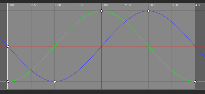
Red = X; Green = Y; Blue = Z || Circle in YZ plane starting movement in -Y direction.
And with the up vector flip logic added, it looks like this:
Looking good!
Except there's a massive problem. This all works fine if the movement is constrained to a plane (in this case the YZ plane, but also works perfectly in the XZ plane), but breaks down if the circular movement is drawn eve slightly off-axis. Here's what happens:
There's a section where everything flips. The size of that section is determined by the magnitude of X, and relates to the part of the graph pointed to in this diagram:
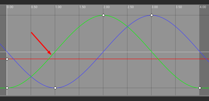
Here X is set at a constant -0.2.
As soon as the Y value passes the value of X and approaches zero, the value in X starts having greater and greater influence over the direction, and then as Y starts moving further away from zero again, the influence drops away again. Although this makes sense, it's not what I want, and I can't figure out how to achieve what I want. I'm having trouble even defining the nature of the problem. Perhaps (probably) I'm doing this in a really stupid way, and there's a much simpler solution for what I'm trying to achieve. I could really use some help!
Given a progression of known locations through 3D space, what is the best way to move an object along them such that its axes bank (if that's the correct term) realistically and don't do any weird flipping around? All help massively appreciated!