[size="5"]What
3D Clipping is a pretty basic function of any 3D renderer. Contrary to popular belief, it is faster and easier than performing clipping in 2D (at the polygon level or at the scanline level.)
Note that the 3D clipper I will present will result in convex n-gons (i.e. non-triangular polygons.) These can then be split into triangles, if you do not support n-gons. See WWH #3 for details on rendering convex n-gons.
[size="5"]Why
This should be pretty obvious. But to be complete, I'll explain. Clipping prevents polygons that intersect the visual screen, yet don't completely fit on-screen, and must be clipped to that screen.
There is another advantage of 3D clipping over 2D clipping. There are problems when a point is projected into 2D that is very close to the view plane. These points can project to near infinity, and cause problems during clipping and projection.
Also, due to the process of scaling the matrix to the view angle, projection is a simpler task.
Finally, there is a nice speedup gained when coding vertices as on-screen or off-screen.
[size="5"]How
Polygons that exist in world space are typically transformed by a matrix (either 3x3 or 4x4.) Many believe that 3D clipping to the view volume can only take place with a homogenous matrix. This document explains how to perform the same clipping with a 3x3 matrix (preventing many people from having to change a lot of their existing framework.) The transformation matrix must be scaled. This will incorporate a portion of the projection into the matrix itself. By doing this, the view volume may be "warped" into an appropriate shape for the desired FOV.
Following the transform, the polygons are clipped to the view volume. Note that this happens PRIOR to projection. This process prevents any polygons from extending off-screen once projected. Finally, polygons are projected and rendered.
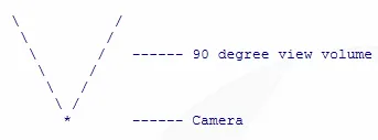
To fully understand the task at hand, and the solution, let's start with a simple diagram of an above-view of the view frustum (with +X extending to the right and +Z extending upwards on the diagram):
Note that the trick here is that the view volume is exactly 90 degrees (I'll address how to change this in a bit.) The beauty of a 90 degree volume is simply that along the right edge of the view volume (and the right-edge of the screen) X will always be equal to Z. The same property also applies to the remaining edges.
In case this isn't clear, notice the diagram above. Assuming a 90 degree angle between each line of the volume, then each line extends at 45 degrees from the camera point. And a 45 degree angle has the nice property of having a perfect 1:1 ratio of X to Y. However, in 3-Space, that becomes a 1:1 ratio between [X to Z] for the left/right edges and [Y to Z] for the top/bottom edges.
So, for a 90 degree view volume, the following is true for all points along the edges of the screen:
 Clipping table
 ------------------------------
 Along the left edge : X = -Z
 Along the right edge : X = Z
 Along the top edge : Y = Z
 Along the bottom edge: Y = -Z
Extending this, let's talk about vertex coding. I'll assume you understand the basic principle. A vertex can be determined off-screen if either of the two following conditions is true:
 |X| > Z
 -or-
 |Y| > Z
Very few applications can make use of a 90 degree view alone. So, to correct for any field of view, the transformation matrix must be modified. This is a simple modification, and is applied to the matrix prior to any transforms, so the cost is negligable. Note that this will force a perspective transform, and the resulting matrix will no longer be a normalized matrix. The operation is simple. I'll use the 3x3 matrix as an example.
The typical 3x3 transformation matrix consists of three unit vectors: X, Y & Z. By simply scaling the X and Y vectors to the perspective scale, your matrix is ready for 3D clipping and perspective transforms. This will allow us to use any FOV, while maintaining our nice 1:1 ratio because the resulting X & Y vertex components have been properly scaled. You may also use a homogenous matrix for this process.
Once the matrix has been properly scaled, the perspective calculations become a bit simpler. Typically, with a non-perspective matrix, a perspective calculation might look like this:
relative_z = 1.0f / (vertex_z - camera_z);
 screen_x = vertex_x * perspective_scale_x * relative_z;
screen_y = vertex_y * perspective_scale_y * relative_z;relative_z = 1.0f / (vertex_z - camera_z);
screen_x = vertex_x * relative_z;
screen_y = vertex_y * relative_z;Off-screen to the left : X < -Z
Off-screen to the right : X > Z
Off-screen to the top : Y < -Z
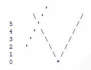
Off-screen to the bottom: Y > ZIf the intersection of the dotted line (a polgyon edge) and the view volume's left-edge is at [Z = 5] then it is known that the crossing happens at [X = -Z], or X = -5 (according to the clipping table above.) This is true even for non-90 degree FOV angles since the transformed vertices are in perspective. Therefore, we can treat non 90-degree FOVs as if they were 90-degrees and get nicely accurate results.
Polygons are clipped an edge at a time, and each edge is clipped to the four conditions:
X clipped to -Z
 X clipped to Z
 Y clipped to -Z
Y clipped to ZActual clipping of edges occurs in the same way any 3D line is clipped to a point it crosses.
As mentioned above, this will result in polygons that may have more edges than their non-clipped representation. These polygons will have to be drawn in that way, or reduced to a set of triangles for your renderer.
A final note on accuracy. Some clipping procedures may suffer from minor inaccuracies due to lack of precision in flaoting point or fixed point math. A simple "fix" is to clamp all clipped vertex X and Y compoonents to the appropriate Z value:
if (x < -z) x = -z;
 if (y < -z) y = -z;
 if (x > z) x = z;
 if (y > z) y = z;


