
Abstract
This article discusses how axonometric projections may be used in computer graphics, multimedia applications and computer games. It compares the axonometric projection, or parallel perspective, to the linear perspective, lists the major properties and tackles some implementation details. The focus of this paper is on the isometric and dimetric projections, the most widely used varieties of the axonometric projection. This paper also presents two dimetric projections that are suitable for (tiled) computer graphics.This article was originally published to GameDev.net in 2001. It was revised by the original author in 2008 and published in the book Advanced Game Programming: A GameDev.net Collection, which is one of 4 books collecting both popular GameDev.net articles and new original content in print format.
Introduction --first attempt
In the Western world, we are accustomed to the linear perspective, which tries to achieve visual realism in paintings of 3-dimensional environments. The linear perspective, which was perfected throughout the 17th century in Europe, is based on Euclidean optics: the eye as a point object that catches straight light rays and that senses only the colour, the intensity and the angle of the rays, not their length. Another perspective had developed in oriental art: the "Chinese perspective" was an intrinsic part of the classical scroll painting (actually, "Chinese perspective" is a bit of a misnomer because the same perspective was also used in Japanese art and that of other oriental countries). A typical Chinese scroll painting had a size of approximately 40 centimetres high by several meters wide. One views the painting by unrolling it (from right to left) on a table in segments of about 60 centimetres wide. The Chinese scroll paintings show a development in time --a form of "narrative art", in contrast to the paintings that were made in Europe at the time, which show a "situation" rather than a development. For these scroll paintings, the Chinese painters needed a perspective that had no explicit vanishing points; every scene of the scroll painting would be seen individually and a vanishing point that lies outside the viewport creates a disoriented view of the scene. (For the same reason, the Chinese scroll paintings usually do not have an explicit light source or cast shadows.) The Chinese painters solved the problem by drawing the lines along the z-axis as parallel lines in the scroll painting. This has the effect of placing the horizon at an imaginary line, infinitely high above the painting. The axonometric projection is a technical term for a class of perspectives to which the Chinese parallel perspective also belongs. These perspectives are not only lacking a vanishing point, they also have a few other, mostly useful, characteristics. These are discussed below.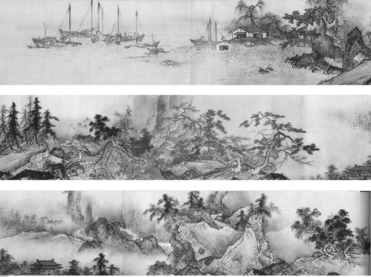 A scroll painting (broken into thirds for printing)
Introduction --second attempt
Technical drawings need to be precise, accurate and unambiguous. Technical drawings are for engineers and fitters. National institutes formally standardize technical drawings, so that a carpenter will build the particular chair that the furniture designer imagined. Technical drawings are a means of communication, for those who can understand it. If the world were populated by engineers, nothing else would matter --but it isn't and engineers (and fitters and carpenters alike) need to communicate with managers and customers. The problem is, of course, that technical drawings are difficult to decipher for the uninitiated. Although they show an object from up to six angles, all of those angles are unrealistic: directly from the front, directly from above, etc. What is needed to convey the general shape of the object is a perspective drawing that shows three sides of a cube at once. At this point, the next issue is: how? Engineers being as they are, they want a simple technique that does not loose much of the accuracy of the original drawings and that does not require artistic skills. Also note that in most cases the object that you must draw does not yet exist, so usually you cannot take a look at the object to get a sense for its proportions. That makes it nearly undoable to adequately position the vanishing points and to estimate the foreshortening.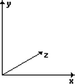
Introduction --third attempt
Computer games have traditionally been brimming with graphics and animation. In fact, games are categorized according to the kind of graphics they used. Two popular types of games are "platform games" where you look from the side, and "board games" where you look mostly from above. These games also have in common that they often use tiles to build the "world" from. Given these similarities, and given the dullness of the unrealistic viewpoints of both platform games and board games, the attempt to make a compromise between these extreme viewpoints is a logical next step. So what one does is take a board of a board game, scale its height (the z-axis) and skew it so that the z-axis on the computer display is a diagonal line. For a better appearance, you can also skew the x-axis. The y-axis remains vertical. This is all that is needed, provided that you get the proportions (for scaling and skewing) right. Due to the coarseness of digital coordinates and the requirement that the edges of (chequerboard) tiles should match precisely, without any pixel overlaps or gaps, the skewing angles and scaling factors that game designers use are an approximation of the visually optimal proportions. One of the simplifications that game designers have made is to use an axonometric projection where a unit along an axis is equally long for all of the three axes. That is, every axis has the same metric; hence, the projection is named "isometric". Axonometric projections and tile-based images are not necessarily related. But most computer games that use an isometric perspective also use tile-based images.And now, onward...
The three questions that occupied me when planning this article were:- What are common (or well-proportioned) axonometric projections, and how persuasive does each look?
- At what angles does one look at board in an axonometric projection? It is tempting to use rendered 3-D objects on an axonometric map, as sprites. To specify the position and orientation of the "camera" in relation to the object, you will need to know the intrinsic angles of the axonometric map that you are using.
- What does one write in an introduction anyway?
- No vanishing points. This allows you to scroll a large image below a viewport and to have the same perspective at any point. In the case of tile-based images, an image is constructed on the fly and need not to have physical bounds or edges.
- Lines that are parallel in the 3-dimensional space remain parallel in the 2-dimensional picture. This is in contrast with the linear perspective, where parallel lines along the z-axis in the 3-dimensional space collapse to a single vanishing point at the horizon in the 2-dimensional picture.
- Objects that are distant have the same size as objects that are close; objects do not get smaller as they move away from the viewer. If you know the scale of the axes, you can measure the size (width, height, length, depth) of an object directly from the picture, regardless of its position on the z-axis; hence the name axonometry.
- The axonometric projections are standardized for technical drawings. These standards are optimized for ease of use versus visual realism. Even if you choose to deviate from the standards, use them as an inspiration. The two projections standardized by the Dutch standardization institute are presented in this paper.
The isometric projection
In an isometric projection, the x-, y- and z-axes have the same metric: a unit (say, a centimetre) along the x-axis is equally long along the y- and z-axes. In other words, if you render a wire frame cube, all edges in the 2-dimensional picture are equally long. Another property of the isometric projection is that the projected wire frame cube is also symmetric. All sides of the projected cube are rhombuses. NEN 2536 (see endnotes) describes an isometric projection that is symmetric with regards to the vertical axis; the angle between the x- and y-axes, and between the z- and y-axes, is 60 degrees. The projection shows three sides of a cube, and the surfaces of each side are equal. The 30? angle between the x- and z-axes and the "horizon" is convenient for technical drawings, because the sine of 30? is 1/2 . This projection is attributed to William Farish who published a treatise about it in 1822 (reference: Jan Krikke). The figure below shows a cube in the isometric projection as defined by NEN 2536.The first object from the left in the figure is the cube unadorned; the second object is the same cube with angles and measures annotated around it. The third and fourth graphics are the top and side views of the perspective scene and they give the camera position that fits the perspective view. The camera position is what you would feed into a 3D renderer (or ray tracer) to create the sprites or tiles for the isometric projection.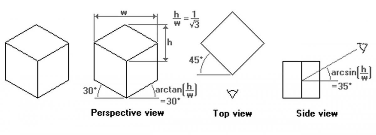 The 30? isometric projection
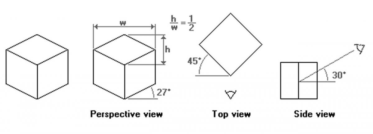 The 1:2 isometric projection
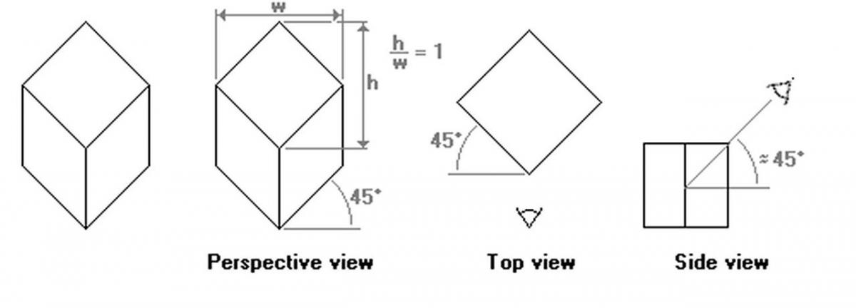 The "military" projection
The dimetric projection
In the dimetric projection, one of the three axes has a different scale than the other two. In practice, the scaled axis is the z-axis and, hence, a cube drawn in a dimetric projection is not a symmetrical graphic (like in the isometric projection). Dimetric projections are more flexible than the isometric projections, as you vary the scale factor (and adjust other parameters in accordance). The asymmetry in the dimetric projection also provides you with an additional angle to play with. From an artistic viewpoint, I also like dimetric projections better than isometric projections, because of the asymmetry. Or rather, the symmetry of an isometric projection makes the scene look "artificial" or surrealistic. Another advantage is, in a computer game, that if you mirror the graphics of a dimetric projection, you are looking at a scene in a new, "fresh", perspective, while the basic computations for the coordinate system stay the same. NEN 2536 also presents a dimetric projection for technical drawings. It is summarized in the figure below. Any distance along the z-axis (drawn at 42?) is scaled at a factor 1/2 .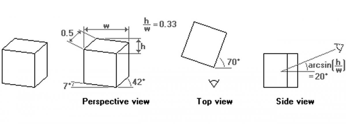 The 42?/7? projection
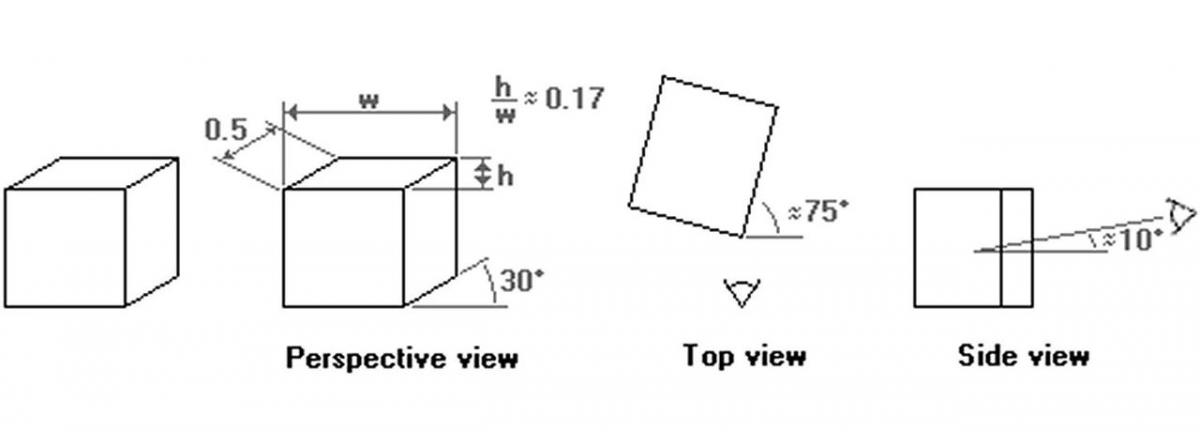 The "Chinese perspective"
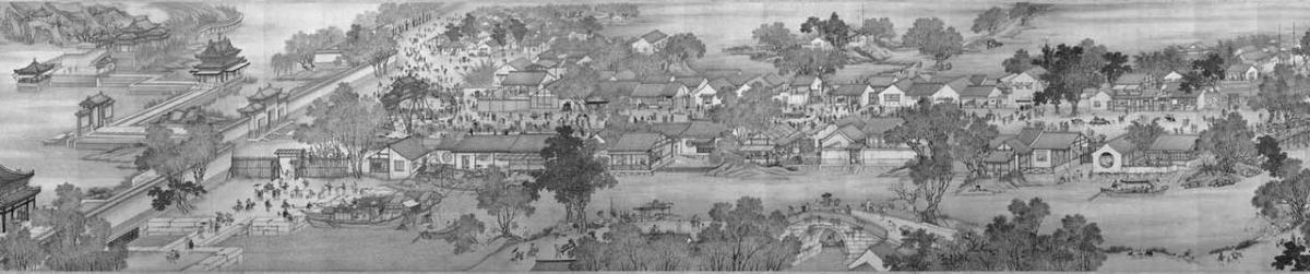 A reproduction from an 18th century remake of an 11-meter handscroll by artists of the Qing court, published in "A City of Cathay"
Dimetric projections for computer graphics and games
As was the case with the isometric projection, in computer graphics some angles are preferable to others. The first dimetric projection that I propose for (tiled) computer graphics is very similar to the projection of Chinese scroll paintings. The difference is the scale of the z-axis, and the angle that it makes with the x-axis. To start with the angle, the z-axis is slanted with approximately 27 degrees (the exact angle is "arctangent(0.5)"). This is the same angle as the isometric projection for computer graphics uses. The scale is such that the width of the side view of a cube, when measured along the x-axis, is half of the width of the front face. The key phrase in the previous sentence is "when measured along the x-axis". In the two former projections, the scale factor applied to distances measured along the z-axis.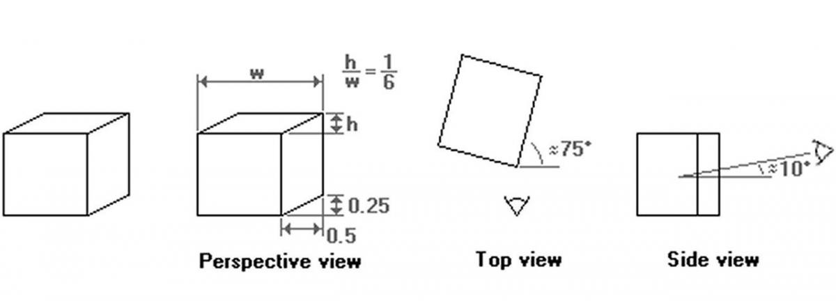 Dimetric 1:2 projection "side-view"
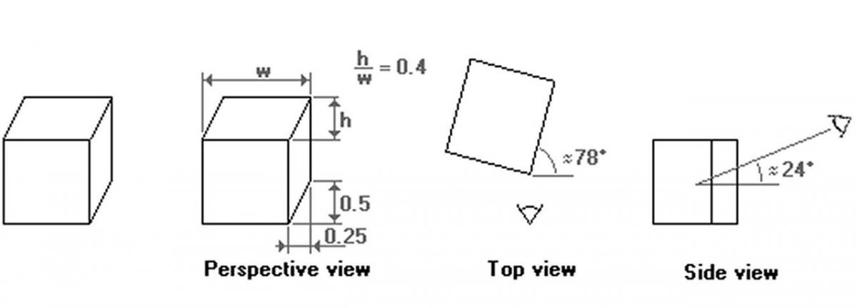 Dimetric 1:2 projection "top-view"
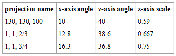
Moving across an axonometric projection
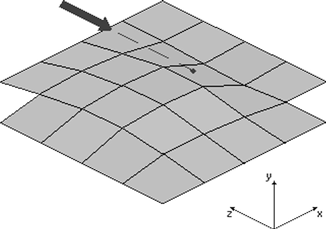
Converting from space coordinates (x,y,z) to a pixel coordinate (x',y') in the projection requires only trivial geometry. The table below presents the formulae for completeness (also refer to the coordinate system in the figure near the top of this paper for my definition of the x-, y- and z-axes).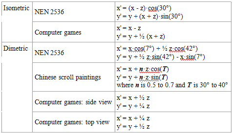
Further information
Cultural Cafe, The; "A City of Cathay: View Chinese Life through a Famous Painting"; CD-ROM; Volume 2; no date.This CD-ROM contains a detailed presentation of the famous scroll painting.
Foley, James D. [et al.]; "Computer Graphics: Principles and Practice"; Addison-Wesley; second edition, 1990; ISBN 0-201-121107.This encyclopaedic book covers perspective projections in chapter five.
Krikke, J.; "Axonometry: A Matter of Perspective"; IEEE Computer Graphics and Applications; July/August 2000.A (historic) overview of axonometric projections from the viewpoints of oriental art, technical drawings and computer games --in the same spirit as the three introductions to this paper, but in a more detailed and coherent article. The article argues that the word "axonometry" should refer only to the particular projection used by oriental artists (the so-called "Chinese perspective") whereas the generic term is "orthographic projections". Citing NEN 2536 and Foley [et al.] as a reference, I treat axonometric projections and parallel projections as synonyms, while an orthographic projection is one where the viewing direction is perpendicular to a plane, showing no perspective at all.
NEN 2536; "Engineering drawing. Axonometric projection"; Nederlands Normalisatie Instituut; August 1966.A Dutch standard for axonometric projections for technical drawings.
Trevisan, Camillo; the CARTESIO program; version 3.03e.An educational and interactive application that features many geometric projections. It is free for personal use.


Useful information, thanks! I will have this article on my hard drive for the rest of my days. I researched isometric projections a few years ago and I couldn't find much that was digestible.