Advertisement

Bump map to normal map

Started by March 29, 2022 07:23 AM
13 comments, last by JoeJ 2 years, 9 months ago

What's the proper way to convert a bump map (one channel) to a normal map? Obviously it's going to be something like a gradient. The brutal approach would simply be to difference with the adjacent pixels and use those differences to make a vector.

normx = (pix[i,j] - pix[i-1,j]) + pix[i+1,j] - pix[i,j])
normy = (pix[i,j] - pix[i,j-1]) + pix[i,j+1] - pix[i,j])
norm = vec3(norm, normy, bumpscale).normalize()

where bumpscale is a scaling factor for the height map.

This might produce jaggyness. Is it customary to look at more pixels, do some smoothing, or something? There seems to be a standard way to do this, but I can't find it documented.

You can search github with something like “normal map bump” and get several examples that seem to be something you could use, based on the descriptions I see when I search. I just searched “normal map” and got many more hits that may be more useful than including the keyword bump, but there is also a lot more cruft you have to navigate.

🙂🙂🙂🙂🙂<←The tone posse, ready for action.

Advertisement

Nagle said:
This might produce jaggyness. Is it customary to look at more pixels, do some smoothing, or something? There seems to be a standard way to do this, but I can't find it documented.

For 2D erosion sim i did the gradients by summing up all 8 neighbors. It helped to prevent features from becoming axis aligned.

Here some example function, but it's pretty ugly research code.
The main question is how to weight the neighbors. If you think of a box filter of size 2x2 texels, the diagonal neighbors have half the weight than the direct neighbors, so i used that.

	void CalcNormalsAndScalarCurvatureFromHeight (int GRID_RES,
		std::vector<Vec4> &normalMapW,
		const std::vector<Vec4> &heightVelMapR)	
	{
		int GRID_MASK = GRID_RES-1;

		//float div = 1.f / float(GRID_RES);
		float pipelen = u_PipeLen;
		float heightScale = 1.f / u_heightScale;
		float div = 1.f / float(GRID_RES);
		//bool B0 = config2.GetParamB ("_tempB0", 0);
		//bool B1 = config2.GetParamB ("_tempB1", 0);
		
		constexpr int lutUO[8] = { 0,  1,  0, -1,  1,  1, -1, -1};
		constexpr int lutVO[8] = {-1,  0,  1,  0, -1,  1,  1, -1};

		for(int iV = 0; iV < GRID_RES; iV++) 
		for(int iU = 0; iU < GRID_RES; iU++)
		{
			int i = iV * GRID_RES + iU;

			bool atBoundary = false;
			if (boundary!=Boundary::Tiled)
				atBoundary = (iU==0 || iV==0 || iU == GRID_MASK || iV == GRID_MASK);

			real h = heightVelMapR[i][TERRAIN] * heightScale;
			vec4 normalCurv;
			if (1 && !atBoundary) 
			{
				//normal = CalcHeightMapNormalAndCurvature (heightVelR.data(), iU, iV, GRID_RES, TERRAIN, 1/u_heightScale);

				real h0 = heightVelMapR[ ((iU-1) & GRID_MASK)	+ (iV & GRID_MASK)		* GRID_RES ][TERRAIN] * heightScale;
				real h1 = heightVelMapR[ ((iU+1) & GRID_MASK)	+ (iV & GRID_MASK)		* GRID_RES ][TERRAIN] * heightScale;
				real h2 = heightVelMapR[ (iU & GRID_MASK)		+ ((iV-1) & GRID_MASK)	* GRID_RES ][TERRAIN] * heightScale;
				real h3 = heightVelMapR[ (iU & GRID_MASK)		+ ((iV+1) & GRID_MASK)	* GRID_RES ][TERRAIN] * heightScale;

				real avH = (h0+h1+h2+h3) * 2.f;

				real d = 2.f * div;
				Vec3 dU (d, h1 - h0, 0);
				Vec3 dV (0, h3 - h2, d);
				Vec3 norm = normalize(cross(dV, dU));

				// diagonal
				{
					real h0 = heightVelMapR[ ((iU-1) & GRID_MASK) + ((iV-1) & GRID_MASK) * GRID_RES ][TERRAIN] * heightScale;
					real h1 = heightVelMapR[ ((iU+1) & GRID_MASK) + ((iV-1) & GRID_MASK) * GRID_RES ][TERRAIN] * heightScale;
					real h2 = heightVelMapR[ ((iU-1) & GRID_MASK) + ((iV+1) & GRID_MASK) * GRID_RES ][TERRAIN] * heightScale;
					real h3 = heightVelMapR[ ((iU+1) & GRID_MASK) + ((iV+1) & GRID_MASK) * GRID_RES ][TERRAIN] * heightScale;
		
					avH += (h0+h1+h2+h3);

					real d = 2.828427f * div;
					Vec3 dU ( d, h3 - h0,  d);
					Vec3 dV ( d, h1 - h2, -d);

					norm += normalize(cross(dU, dV)) / 2;
					norm = normalize(norm);
				}

				avH /= 12.f;

				normalCurv = Vec4(norm, h - avH);
			}
			else
			{
  //  7   0   4
  //  3   c   1
  //  6   2   5
				float count = 0;
				float curv = 0;
				Vec3 norm (0);
				for (int n=0; n<4; n++)
				{
					int oU1 = lutUO[n+4];
					int oV1 = lutVO[n+4];
					int aU1 = iU+oU1;
					int aV1 = iV+oV1;
					if (aU1 < 0 || aV1 < 0 || aU1 >= GRID_RES || aV1 >= GRID_RES)
						continue;
					int ai1 = aV1 * GRID_RES + aU1;
					real h1 = heightVelMapR[ai1][TERRAIN] * heightScale;
					Vec3 d1 ( div*oU1, h1 - h, div*oV1);
					curv += h1;
					count += 1;

					int oU0 = lutUO[n];
					int oV0 = lutVO[n];
					int aU0 = iU+oU0;
					int aV0 = iV+oV0;

					if (!(aU0 < 0 || aV0 < 0 || aU0 >= GRID_RES || aV0 >= GRID_RES))
					{
						int ai0 = aV0 * GRID_RES + aU0;

						real h0 = heightVelMapR[ai0][TERRAIN] * heightScale;
						Vec3 d0 ( div*oU0, h0 - h, div*oV0);
						//RenderVector(Vec3((iU+.5f)*div,h,(iV+.5f)*div), d0*.5f, 1,0,0);
						//RenderVector(Vec3((iU+.5f)*div,h,(iV+.5f)*div), d1*.5f, 0,1,0);
						norm += cross(d1, d0);
						curv += h0;
						count += 1;
					}

					oU0 = lutUO[(n+1)&3];
					oV0 = lutVO[(n+1)&3];
					aU0 = iU+oU0;
					aV0 = iV+oV0;

					if (!(aU0 < 0 || aV0 < 0 || aU0 >= GRID_RES || aV0 >= GRID_RES))
					{
						int ai0 = aV0 * GRID_RES + aU0;
						
						real h0 = heightVelMapR[ai0][TERRAIN] * heightScale;
						Vec3 d0 ( div*oU0, h0 - h, div*oV0);
						//RenderVector(Vec3((iU+.5f)*div,h,(iV+.5f)*div), d0*.4f, 1,0,0.5f);
						//RenderVector(Vec3((iU+.5f)*div,h,(iV+.5f)*div), d1*.4f, 0,1,0.5f);
						norm += cross(d0, d1);
						curv += h0;
						count += 1;
					}
				}
				//ImGui::Text("count %f", count);
				normalCurv = Vec4(normalize(norm), 0);//h - (curv / count)); // curvature too faulty - would need to reflect
			}

			normalMapW[i] = normalCurv; 
		}
	} 

I agree about considering the diagonal neighbors. I was thinking that the diagonal neighbors should have 1/sqrt(2) weight, though, because the distance to them is sqrt(2).

Nagle said:
I was thinking that the diagonal neighbors should have 1/sqrt(2) weight, though, because the distance to them is sqrt(2).

I had the same thoughts, but did not find any explanation about ‘this is the one and only correct way to calculate gradients!’.

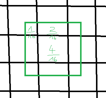
But distance is a incomplete metric, as it ignores the solid angles of multiple samples. My decision was based on area integration:

The green rectangle is the box filter kernel, and looking at area we see diagonals have exact half area of a direct neighbor.
However, if we choose a different size of area to integrate, you could get a solution where 1 / sqrt(2) is right too.
Seems a matter of trial and error and looking what works best for you.

However, there's one thin in my code i'm really unsure about. I do:

norm = normalize(normalFromDirectNeighbours * 2 + normalFromDiagonals);

Which means the two normals are already normalized, messing up their weighting?

I think it would be more correct to do this instead:

norm = normalize(gradientFromDirectNeighbours * 2 + gradientFromDiagonals);

But really not sure about anything. :/

I think it would be more correct to do this instead:

norm = normalize(gradientFromDirectNeighbours * 2 + gradientFromDiagonals);

Ha, no - the diagonal gradient now needs to compensate for larger distances, so that's where sqrt(2) comes in:

norm = normalize(gradientFromDirectNeighbours * 2 + gradientFromDiagonals * 1/sqrt(2));

This would be most correct now, maybe ;D

Advertisement

JoeJ said:
norm = normalize(gradientFromDirectNeighbours * 2 + gradientFromDiagonals * 1/sqrt(2));

2 vs 0.707?

Nagle said:
2 vs 0.707?

Yes, because the distance to the diagonals was larger, the gradient is larger than the other to the direct neighbors.
Or not? Does distance just cancel out? I'm unsure again.

To verify, we could make a heightmap of a sphere. Then all normals should point to the center. We could sum up error and compare various approaches which gives least error.

I did this for the water simulation, by dropping a drop and making sure the wave forms an exact circle. But that was slightly different math, and i did not such test for the normals calculation.
I was too lazy. Let me know if you're not… ;)

The best method that I know of to calculate the image gradient is by convolution with the derivative of a Gaussian function. This will not exhibit any of the artifacts which you might see with simpler approaches like those discussed above. This filter kernel is separable, similar to gaussian blur, which means that to calculate the X derivative, you convolve with a gaussian deriviative in X direction and regular gaussian in the Y direction. The guassian derivative function can be calculated analytically. The size of the filter kernel determines the “scale” at which the derivative is calculated. You can get very nice results by calculating derivatives at multiple scale factors and then doing a weighted combination of those scales to get the final normal map.

See these slides for some more information.

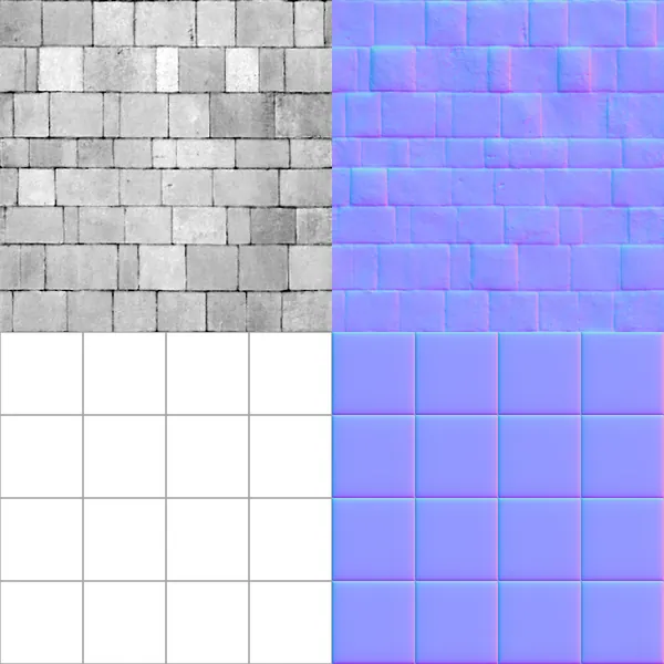
Here is an example of this approach (using the multi-scale derivatives). Note how the normal maps look smoother and “rounded” because of the use of derivatives at larger than 1-pixel scale.

Aressera said:
This will not exhibit any of the artifacts which you might see with simpler approaches like those discussed above.

You get higher quality from a larger kernel at the cost of loosing high frequencies, proven from the rounding of the tiles at the bottom image. Notice this rounding does not agree with the grid image on the right, which is just black and white.
If you reduce a gaussian kernel to a 3x3 region, it may even show more ‘issues’ than from the trial to consider all factors geometrically correctly.

I think i'll code some test to be sure. As i use this quite often, it's worth the time…

This topic is closed to new replies.

Advertisement