Advertisement

Understanding D3D11 basics

Started by June 28, 2015 10:10 PM
10 comments, last by bigworld12 9 years, 6 months ago

hello every one ,
i have this code here


Dim desc = New SwapChainDescription() With {
                 .BufferCount = 1,
                 .ModeDescription = New ModeDescription(m_rendrform.ClientSize.Width,
                                                        m_rendrform.ClientSize.Height,
                                                        New Rational(60, 1),
                                                        Format.R8G8B8A8_UNorm),
                 .IsWindowed = True,
                 .OutputHandle = m_rendrform.Handle,
                 .SampleDescription = New SampleDescription(1, 0),
                 .SwapEffect = SwapEffect.Discard,
                 .Usage = Usage.RenderTargetOutput}
 
 
            ' Create our device with swap chain and get the device context
            Direct3D11.Device.CreateWithSwapChain(DriverType.Hardware,
                                                  DeviceCreationFlags.None,
                                                  desc,
                                                  _d3d11Device,
                                                  _swapChain)
 
            _d3d11DevCon = _d3d11Device.ImmediateContext
 
            _factory = _swapChain.GetParent(Of Factory)()
            _factory.MakeWindowAssociation(m_rendrform.Handle, WindowAssociationFlags.IgnoreAll)
 
            ' New RenderTargetView from the backbuffer
            backBuffer = Texture2D.FromSwapChain(Of Texture2D)(_swapChain, 0)
            _renderTargetView = New RenderTargetView(_d3d11Device, backBuffer)
 
            ' Compile Vertex and Pixel shaders
            vertexShaderByteCode = ShaderBytecode.CompileFromFile("MyPointsShaders.fx", "VS", "vs_4_0", ShaderFlags.None, EffectFlags.None)
            vertexShader = New VertexShader(_d3d11Device, vertexShaderByteCode)
 
            pixelShaderByteCode = ShaderBytecode.CompileFromFile("MyPointsShaders.fx", "PS", "ps_4_0", ShaderFlags.None, EffectFlags.None)
            pixelShader = New PixelShader(_d3d11Device, pixelShaderByteCode)
 
            ' Layout from VertexShader input signature
            layout = New InputLayout(_d3d11Device,
                                     ShaderSignature.GetInputSignature(vertexShaderByteCode),
                                     {New InputElement("POSITION", 0, Format.R32G32B32A32_Float, 0, 0),
                                      New InputElement("COLOR", 0, Format.R32G32B32A32_Float, 16, 0)})
 
            ' Instantiate Vertex buiffer from vertex data
            vertices = Direct3D11.Buffer.Create(
                _d3d11Device,
                BindFlags.VertexBuffer,
                {New Vector4(0.0F, 0.5F, 0.5F, 1.0F), New Vector4(1.0F, 0.0F, 0.0F, 1.0F),
                 New Vector4(0.5F, -0.5F, 0.5F, 1.0F), New Vector4(0.0F, 1.0F, 0.0F, 1.0F),
                 New Vector4(-0.5F, -0.5F, 0.5F, 1.0F), New Vector4(0.0F, 0.0F, 1.0F, 1.0F)})
 
            ' Prepare All the stages
            _d3d11DevCon.InputAssembler.InputLayout = layout
            _d3d11DevCon.InputAssembler.PrimitiveTopology = PrimitiveTopology.PointList
            _d3d11DevCon.InputAssembler.SetVertexBuffers(0, New VertexBufferBinding(vertices, 32, 0))
            _d3d11DevCon.VertexShader.Set(vertexShader)
            _d3d11DevCon.Rasterizer.SetViewport(New Viewport(0,
                                                             0,
                                                             m_rendrform.ClientSize.Width,
                                                             m_rendrform.ClientSize.Height,
                                                             0.0F, 1.0F))
            _d3d11DevCon.PixelShader.Set(pixelShader)
            _d3d11DevCon.OutputMerger.SetTargets(_renderTargetView)

this simply shows a black screen with a red dot on it (you can hardly see it)

76cef1cf641738c4b6b85ca21e98d3a3.png

so i have some questions :

1 - how to change location of the dot

2 - how to change color of the dot

3 - what are the pieces of the code that i posted that are responsible for "Drawing" objects

4 - how to change the black background

5 - are there any helpful tutorials for sharpdx with D3D11 ?

1 - how to change location of the dot


That will be determined by your vertex data most likely. You are creating the buffer with the code New VertexBufferBinding(vertices, 32, 0) and defining the data in the buffer with your `vertices` array, which you have not shown.

2 - how to change color of the dot


Controlled by your pixel shader (for the most part), which you have not shown.

3 - what are the pieces of the code that i posted that are responsible for "Drawing" objects


Nothing you have posted in responsible for drawing. You have posted a subset of the data and state setup code for your frame, but nothing that actually tells the GPU to actually do anything with that data.

4 - how to change the black background


Draw something there. Or clear your render target with a chosen color.

5 - are there any helpful tutorials for sharpdx with D3D11 ?


So far as I can tell, yes. I'm not a prolific C# or VB.net coder myself, so I don't have any to recommend that I can vouch for. Is there anything specific you're looking for that you can't find via Google? (There are few tutorials for VB.net, which is unsurprising given that C++ - and to a lesser extent C# - dominate the game programming industry.)

Sean Middleditch – Game Systems Engineer – Join my team!

Advertisement

1 - the vertices array :


 vertices = Direct3D11.Buffer.Create(
                _d3d11Device,
                BindFlags.VertexBuffer,
                {New Vector4(0.0F, 0.5F, 0.5F, 1.0F), New Vector4(1.0F, 0.0F, 0.0F, 1.0F),
                 New Vector4(0.5F, -0.5F, 0.5F, 1.0F), New Vector4(0.0F, 1.0F, 0.0F, 1.0F),
                 New Vector4(-0.5F, -0.5F, 0.5F, 1.0F), New Vector4(0.0F, 0.0F, 1.0F, 1.0F)})

2 - pixel shader :


 vertexShaderByteCode = ShaderBytecode.CompileFromFile("MyPointsShaders.fx", "VS", "vs_4_0", ShaderFlags.None, EffectFlags.None)
            vertexShader = New VertexShader(_d3d11Device, vertexShaderByteCode)
 
            pixelShaderByteCode = ShaderBytecode.CompileFromFile("MyPointsShaders.fx", "PS", "ps_4_0", ShaderFlags.None, EffectFlags.None)
            pixelShader = New PixelShader(_d3d11Device, pixelShaderByteCode)

and the MyPointsShaders.fx is


struct VS_IN
{
	float4 pos : POSITION;
	float4 col : COLOR;
};

struct PS_IN
{
	float4 pos : SV_POSITION;
	float4 col : COLOR;
};

PS_IN VS(VS_IN input)
{
	PS_IN output = (PS_IN)0;

	output.pos = input.pos;
	output.col = input.col;

	return output;
}

float4 PS(PS_IN input) : SV_Target
{
	return input.col;
}

technique10 Render
{
	pass P0
	{
		SetGeometryShader(0);
		SetVertexShader(CompileShader(vs_4_0, VS()));
		SetPixelShader(CompileShader(ps_4_0, PS()));
	}
}

3 - it doesn't matter for me if i use c# or vb.net it's just that i prefer vb.net more when learning new things


1 - how to change location of the dot

Although, as SeanMiddleDitch mentions, you haven't shown any code yet for drawing the points, it appears you're rendering in normalized device coordinates. I.e., the coordinates (x,y) of your backbuffer/window display run from upper-left (-1, +1) to lower-right (+1, -1). The vertex data you posted indicates your intent is to render 3 points at screen positions:

- red color, middle of the screen, 1/4 of the screen height from the top

- green color, 3/4 of the screen width from the left, 3/4 of the screen height from the top

- blue color, 1/4 of the screen width from the left, 3/4 of the screen height from the top

How or whether they get rendered depends on how you clear the depth buffer, whether you have depth testing enabled or not, and what the depth testing criteria is.

You have several choices to change the location of the points:

a. if you mean changing the location just for your single display, change the hard-coded vertex data X and Y coordinates - X within the range -1 to +1 (left side of screen to right side of screen), and Y within the range +1 to -1 (top of the screen to the bottom of the screen).

b. if you mean change the location dynamically over time, either:

1. re-create your vertex buffer each time increment (not recommended)

2. load a constant buffer each frame with a time-related parameter (such as a translation matrix), and, in the vertex shader, multiply the vertex position by that parameter.

There are other possibilities but you haven't said exactly what you mean by changing the positions.


2 - how to change color of the dot

Change the color parameter in the vertex structure. As posted above, you have red, green and blue dots. Change those as desired.

EDIT - You can also change the color in the vertex shader or pixel shader by loading a constant buffer with a multiplier, divisor or other parameter, and changing the color in the vertex or pixel shader.

E.g.,

White - (1, 1, 1, 1)

Purple - (1, 0, 1, 1)

Orange - (1, 1, 0, 1)

Magenta - (0, 1, 1, 1)


[ your other questions ]

See SeanMiddleDitch's answers above.

Please don't PM me with questions. Post them in the forums for everyone's benefit, and I can embarrass myself publicly.

You don't forget how to play when you grow old; you grow old when you forget how to play.

ok here is my current progress

1 - i managed to change background dynamically on my interact or automatically


 _d3d11DevCon.ClearRenderTargetView(_renderTargetView, GetColor4(BackGround))

2 - i decided i will make a triangle instead , so i changed to this


_d3d11DevCon.Draw(3, 0) 'insted of 1

  Dim MyVertexes() As Vector3 = {New Vector3(0.0F, 0.5F, 0.0F),
                                           New Vector3(0.45F, -0.5F, 0.0F),
                                           New Vector3(-0.45F, -0.5F, 0.0F)}
            verticesBuffer = Direct3D11.Buffer.Create(
                _d3d11Device,
                BindFlags.VertexBuffer,
               MyVertexes)
            _d3d11DevCon.InputAssembler.InputLayout = layout
            _d3d11DevCon.InputAssembler.PrimitiveTopology = PrimitiveTopology.TriangleList
            _d3d11DevCon.InputAssembler.SetVertexBuffers(0, New VertexBufferBinding(verticesBuffer, 32, 0))
            _d3d11DevCon.VertexShader.Set(vertexShader)
            _d3d11DevCon.Rasterizer.SetViewport(New Viewport(0, 0,
                                                             m_rendrform.ClientSize.Width,
                                                             m_rendrform.ClientSize.Height,
                                                             0.0F, 1.0F))

but it isn't working

and i fail to see why is this not working since it's a perfect triangle

i got the whole code from here https://github.com/sharpdx/SharpDX-Samples/tree/master/Desktop/Direct3D11/MiniTri

and i just changed the vertexes but it shows this

32e2461c5091104ad0a739ddae0f1966.png

the thing is : -

this code :


Dim vertixes2 = {New Vector4(0.0F, 0.5F, 0.5F, 1.0F),
                             New Vector4(1.0F, 0.0F, 0.0F, 1.0F),
                             New Vector4(0.5F, -0.5F, 0.5F, 1.0F),
                             New Vector4(0.0F, 1.0F, 0.0F, 1.0F),
                             New Vector4(-0.5F, -0.5F, 0.5F, 1.0F),
                             New Vector4(0.0F, 0.0F, 1.0F, 1.0F)}

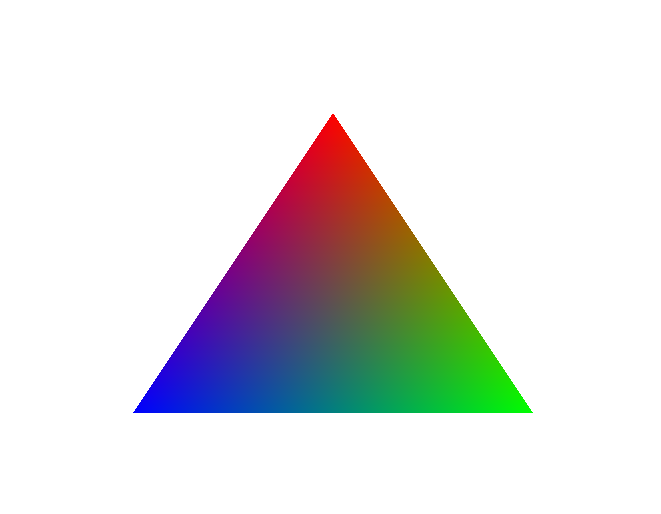
shows this

62cc979f8e34460b20f6bc015eb8ae9b.png

but this code :


 Dim MyVertexes() As Vector3 = {New Vector3(0.0F, 0.5F, 0.0F),
                                           New Vector3(0.45F, -0.5F, 0.0F),
                                           New Vector3(-0.45F, -0.5F, 0.0F)}

shows this

32e2461c5091104ad0a739ddae0f1966.png

Advertisement

In the original code, we have the following:

{
New Vector4(0.0F, 0.5F, 0.5F, 1.0F), //Position of 1st vertex
New Vector4(1.0F, 0.0F, 0.0F, 1.0F), //Color of 1st vertex
New Vector4(0.5F, -0.5F, 0.5F, 1.0F), //Position of 2nd vertex
New Vector4(0.0F, 1.0F, 0.0F, 1.0F), //Color of 2nd vertex
New Vector4(-0.5F, -0.5F, 0.5F, 1.0F), //Position of 3rd vertex
New Vector4(0.0F, 0.0F, 1.0F, 1.0F) //Color of 3rd vertex
}

Positions are in X Y Z.

Colors are in RGBA (Red, Green, Blue, Alpha). Alpha tends to mean translucency in shaders like this.

Hello to all my stalkers.

In the original code, we have the following:


{
New Vector4(0.0F, 0.5F, 0.5F, 1.0F), //Position of 1st vertex
New Vector4(1.0F, 0.0F, 0.0F, 1.0F), //Color of 1st vertex
New Vector4(0.5F, -0.5F, 0.5F, 1.0F), //Position of 2nd vertex
New Vector4(0.0F, 1.0F, 0.0F, 1.0F), //Color of 2nd vertex
New Vector4(-0.5F, -0.5F, 0.5F, 1.0F), //Position of 3rd vertex
New Vector4(0.0F, 0.0F, 1.0F, 1.0F) //Color of 3rd vertex
}

Positions are in X Y Z.

Colors are in RGBA (Red, Green, Blue, Alpha). Alpha tends to mean translucency in shaders like this.

will , this is starting to make sense now

so in no way i can create a Vector3 that does all of the above ?

What you pass through has to match what the shader expects to receive.

If the shader expects 2x Vector4 values per vertex (1 for position and 1 for color), then you need to supply that.

Different shaders can expect different things, for example a single vector position, and the color hard coded in the shader.

Hello to all my stalkers.

What you pass through has to match what the shader expects to receive.

If the shader expects 2x Vector4 values per vertex (1 for position and 1 for color), then you need to supply that.

Different shaders can expect different things, for example a single vector position, and the color hard coded in the shader.

and let me guess , this is what controlling it ?


 var layout = new InputLayout(
                device,
                ShaderSignature.GetInputSignature(vertexShaderByteCode),
                new[]
                    {
                        new InputElement("POSITION", 0, Format.R32G32B32A32_Float, 0, 0),
                        new InputElement("COLOR", 0, Format.R32G32B32A32_Float, 16, 0)
                    });

This topic is closed to new replies.

Advertisement