Advertisement

Aircraft Rotation forces on takeoff. And how the vertical stabalizer works.

Started by February 13, 2015 07:54 AM
4 comments, last by _WeirdCat_ 10 years ago

I am implementing a small game where i simulate a 2d airplane.

I am using the Equation of Lift and Equation of Drag with the Weight Force and Thrust Force.

This is pretty streight forward, and it works like a charm, really cool to see the same stall characteristics like in the real world on the same numbers! =)

But i cant understand the formula for letting the nose lift when you rotate the aircraft.

I dont want to "hack" one of the four fources, i just want to add some "downforce" on the stabalizer that creates and "upforce" on the nose.

But i dont know the relationship/formulas of these forces.

I think it could be like this:

Nose upforce = Thrust * 0.6 - (some constant value so that we cant rotate on small thrust)

I need to lift the nose to get some Angle of attack so the airplane starts to generate lift.

btw Anyone know the angle of attack on a b737 with the vertical stabalizer trimmed to 0?


I dont want to "hack" one of the four fources, i just want to add some "downforce" on the stabalizer that creates and "upforce" on the nose.

It depends on how you want to model the physics and simulate behavior.

EDIT2: With regard to the topic title: the vertical stabilizer doesn't play a roll in rotation about the horizontal axis in the scenario you're asking about.

If you don't want to hack, you need to simulate the flight control surfaces. Rotation occurs due to torque from forces on the control surfaces, more than the fixed surfaces, producing yaw, pitch and roll. Even for a 2D view of the object, you'll need to do a bit of 3D math.

However, if you just want to add some other forces here and there to get the model to get the results you want, that's fine. Simulation is just that - producing something similar to real-world behavior. Pick something that looks acceptable to you.

EDIT: For a more complete simulation, there are two similar and related concepts - force and torque.

Force causes translation of the center-of-mass. Torque causes rotation about the center-of-mass.

The governing equations are:

F = mass * linear-acceleration

Torque = inertial-tensor * angular-acceleration

Please don't PM me with questions. Post them in the forums for everyone's benefit, and I can embarrass myself publicly.

You don't forget how to play when you grow old; you grow old when you forget how to play.

Advertisement

see this topic:

buckeye shows almost everything to get the angular acc

then with the equations of

a - your angular acceleration

//this is for linear velocity not angular

v = v + a*delta_t;

pos = pos + v*delta_t;

but the equations are the same then you will end up with a vector which will be your angular 'translation' for each axis for each control surface.

and you are almost there

the thing is to attach forces that are acting (the rotational part) to the center of pressure of each control surface (elevators, wings) which for slow velocities will be in wing case 1/3 of chord , 1/2 wing span, and mean chord,

lets assume Y is your up vector then according to that:
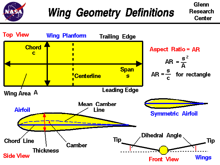
geom.gif

X = span/2 Y = mean choord y val in 1/3 from wing front, Z = 1/3 of chord from front.

the math behind rotation for model itself (when you have your angles) is quite complicated thing. and i wont provide code for it. Alli can say its a rotation aroundrotated local axis.

YOu could use quaterions for that or single sin cos approach and build a rotation matrix.

I dont want to "hack" one of the four fources, i just want to add some "downforce" on the stabalizer that creates and "upforce" on the nose.

since wing center of pressure is not situated in the geometric center of the whole aircraft (not in the axis) it will rotate the plane after lift is sufficient.

and ofc elevator deflection does that too.

This is pretty streight forward, and it works like a charm,

Thats strange i made such simulation based on those 4 forces it diidn't work as it should could you explain your approach?

DId you make force equations with the respoect to the drag./lift coefficients tables? like the wing is divided into lets say two parts one without airlieron and second with it then when you deflect airlieron you change the coefficient or you did something else?

Nose upforce = Thrust * 0.6 - (some constant value so that we cant rotate on small thrust)
I need to lift the nose to get some Angle of attack so the airplane starts to generate lift.

wing shape should generate lift on 0 angle of attack, when not you use flaps to get higher lift coefficient.


btw Anyone know the angle of attack on a b737 with the vertical stabalizer trimmed to 0?

what is vert stab in your meaning?

elevator?

anyway the summary

to pitch nose up or down

you deflect elevator then you apply the force at the point of 1/3 of chord for that elevator etc. then from these equations in the beggining you rotate the by the calculated angle

theres alos the inertia for the plane itself but its mr^2. really read that topic i made;

Thanks all for your answers. And i am sorry for the vertical stabalizer, i was tired when i wrote this question. Of course i mean horizontal stabalizer.

I made a solution that works really well.

After lets say 80 IAS you will be able to rotate the nose. This is done by simulating the pitch of the horiz stab. No fancy math here, just adding the force based on settings.

The plane is really flying pretty good now, hitting the stall speed when expecting and have the rotations like normal 737:s.

I have set the "constant" aoa to 3.5. So basically the aircraft will lift without any pitch at all when hitting speeds around 250-300 IAS. (fully weight)

Now i have two problems more to solve.

What is the best way of translating the Cl and Cd Curves Mathematically?

I can do this with 100 if lines as a mapping table, but it is intresting if you could do something like "closest point on line" and then draw it up as a graph?

Thats what i am thinking about now.


This is pretty streight forward, and it works like a charm,

Thats strange i made such simulation based on those 4 forces it diidn't work as it should could you explain your approach?

DId you make force equations with the respoect to the drag./lift coefficients tables? like the wing is divided into lets say two parts one without airlieron and second with it then when you deflect airlieron you change the coefficient or you did something else?

I have only implemented Weight and Lift. But this is working fine except i miss some drag now. Adding it the stall speed will be spot on.

I just implement the Formula and then using the mapping tables. No fancy thing.


for your question go see that new topic you have made i am just answering it right now.

This topic is closed to new replies.

Advertisement