But it doesn't have to be that way.
Even programmers can learn to use the free tool known as Blender. Blender will allow you to model, UV map, and export your creations to many formats, including the almighty *.x format. The secret to using Blender is its hotkeys. That is where the real speed and great workflow comes from.
In part one of this tutorial we are going to model a sword, and we will not use a single button on the screen. I want you to learn how to model quickly, and that means you will keep your left hand on the keyboard and your right hand on the mouse.
We will start ridiculously simple and by the time we are done you will have the basic knowledge to begin models of your own design. I chose a sword because many games need swords, and modeling one will use the basic commands that you will need for every model.
We will not go into fancy techniques or commands in this tutorial because it is aimed at beginners. You can explore all of the hotkeys by going to the 'Hotkey Reference' in the 'Help' menu.
Part II of this tutorial will show how to UV map the sword and how to properly export it as a *.x file.
I will use some abbreviations during this tutorial, defined as the following:
- LMB = Left mouse button
- MMB = Middle mouse button
- RMB = Right mouse button Most hotkeys involve a single button, or a button in combination with Shift, Alt, or Ctrl. I will use the following conventions when using hotkeys:
(letter to press KEY)
Examples:- (EKEY) Press the 'E' button on your keyboard. This is your extrude command.
- (GKEY) Press the 'G' button on your keyboard. This grabs the current selection and lets you move it.
- (Shift+MMB) Press and hold the Shift key and the middle mouse button. This will pan the current view. I will also on occasion use red circles in the pictures to show which vertices I am referring to.
A few things to keep in mind:- To select an object or vertex in Blender, use the right mouse button (RMB).
- When performing some actions, like Scale (SKEY), Move (GKEY), or Extrude (EKEY), you can cancel the action by right-clicking (RMB). Left-clicking (LMB) accepts the changes.
- To select multiple objects or vertices hold down SHIFT and make your selections with the RMB.
- The SHIFT button will also deselect any selected objects or vertices when used with the RMB.
- To toggle in and out of edit mode for the selected object, use TAB.
- The SPACEBAR is your friend. That is where you find many useful commands and tools, including primitive objects. The 3D Cursor, which looks like a red and white crosshair, is where the new objects will be placed. When you start Blender this will be in the center of your view. You can change its location by left clicking (LMB) anywhere in the view. Keep in mind that it's 3D space, so to get correct placement you may have to adjust it in several views; Front, Side, and/or Top.
- Use (AKEY) to select/deselect all objects. If one or more objects are already selected, but not all of them, (AKEY) will deselect all. Hitting it again will select everything.
- Any window that contains the cursor is the selected view. Simply move the mouse to a different window to make it the current view.
- You can switch your model's appearance from Wireframe to Shaded by using the ZKEY as a toggle switch. There is also the option to show textures and/or materials by using SHIFT+ZKEY as another toggle.
- Change the view in a window using the NUMPAD keys: 1 for front, 3 for side, and 7 for top. Holding the Alt key with 1, 3, or 7 will give you the opposite view.
- Rotate a view using the NUMPAD keys 2, 4, 6, or 8. You can also rotate freely by holding the MMB and dragging the mouse.
- By scrolling the MMB up or down you can zoom in or out of the current view.
- You should save often by using (CTR+WKEY), which is Save, or by using (F2), which is Save As. I'm not going to tell you how often to save, that's a personal preference.
- You can clear up your view while in Edit Mode (Toggle on and off with TAB) by selecting vertices you're not using and Hiding (HKEY) them. Hidden vertices will remain hidden if you leave Edit Mode and then re-enter it. To Unhide them, use ALT+HKEY. With that said, let's begin.
I like to use a three-window setup when modeling:
When you start Blender it has only one window with a camera, light, and plane. Select all three objects (AKEY) and then delete them (XKEY).
To split the window into two views, move your cursor to the top edge of the screen until it turns into a double-arrow and hit your MMB. Click on the "Split Area" button on the menu that pops up. This will cut your window in half.
Since the split always cuts the current view, move your mouse to the right-side window and then move it back to the left border and cut it in half again. This will give you the three-window layout that I use.
Move your mouse to the large window on the left and press NUMPAD 1. This is now your Front View window. Next move your mouse to the top window on the right side and press NUMPAD 7 Now you have a Top View. Finally, change the last window to a Side View with NUMPAD 3.
Let's add a circle to the Top View window by pressing SPACEBAR and going to Add>Mesh>Circle:
Blender will ask you for the number of Vertices you want. You can click on the right or left side arrows on the button or hold down your LMB and drag it left or right to rapidly scroll through the numbers.
We would like 8 vertices for our circle.
We'll need to make the circle oblong. This will be the shape of our handle.
When we create the circle it begins life with all vertices selected and that's how we need it to scale the entire object. Click (SKEY) to begin the scale mode and move your mouse either closer to or away from to make it larger or smaller. What's that? It just makes it bigger or smaller, not oblong? While in Scale mode, click and hold MMB. This scales the object along a specific axis. You can click again on MMB to toggle this effect on or off.
Now scale (SKEY+MMB) the circle to make a nice oblong shape.
Move your cursor to the Front View. Pan (SHIFT+MMB) the Front View to place our circle near the top of the view.
Now, with all vertices still selected, we will Extrude (EKEY) them all straight down until we get a nice sized handle.
As with the scaling, once you enter Extrude mode, just click through the axis options with the MMB until you get the one that makes it go straight along the Z-axis. This ensures we have a straight handle.
To make the pommel we are going to Extrude and Scale it two more times.
The bottom vertices will still be all selected, so we don't have to worry about selecting them.
Extrude (EKEY) it straight down a little bit, and don't forget to use the MMB. Now Scale (SKEY) it, but don't constrain it with the MMB. We want to Scale it all the way around. Extrude (EKEY) it again, a little farther this time, using MMB. Scale (SKEY) it once more, but this time make it smaller than the handle.
You should have something like this:
Time to Rotate the Front View using the MMB. We would like to see the opening at the bottom of the sword:
We can't have that opening there, can we? Once again, the direction in which we Extruded our model leaves us with the correct vertices selected, the very bottom ones lining the opening. We will use the AutoFace (SHIFT+FKEY) tool to fill this in:
That's better. Now let's deselect (AKEY) all vertices and switch to Front View (NUMPAD 1). Pan (SHIFT+MMB) the view to make the top of our handle in the center of the screen. You may Zoom in or out by scrolling the MMB up or down.
Now we want to Select the top row of vertices. This will be easier if we use the (BKEY) which allows us to drag a box around a group of vertices. So drag a box around the top row and Extrude (EKEY) it up just a little bit: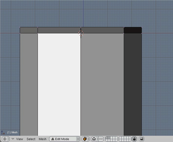
We have to square up the new vertices a bit. Deselect (AKEY) all vertices. Select the two vertices (SHIFT+RMB) that are just to the left and right of the center vertex at the top. This is easier to do if you Rotate (MMB) the Front View slightly.
In Top View move (GKEY) the two vertices up until they are even with the center vertex. Don't forget your MMB. Repeat with the other side.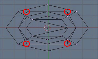
Deselect (AKEY) all vertices. Now we have something like this: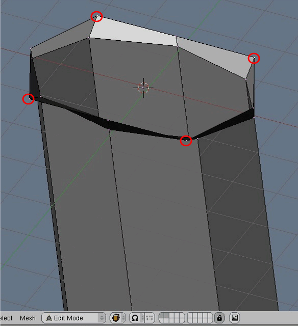
Go back to Front View (NUMPAD 1) and drag a box to select (BKEY) the top 3 vertices on the right side of the model. You will only see 2 of them; the third is directly behind one of the others:
Zoom out (MMB) to make room in the Front View for the crosspiece. With the selected vertices, Extrude (EKEY) them out to the right. Deselect (AKEY) all and repeat on the other side:
Rotate (MMB) the Front View to see your efforts:
Move your cursor to the Side View window and select (BKEY) the entire top row of vertices and Extrude (EKEY) them straight up to make the crosspiece thickness: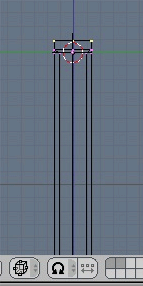
Deselect (AKEY) all. This will now make our Front View look like this: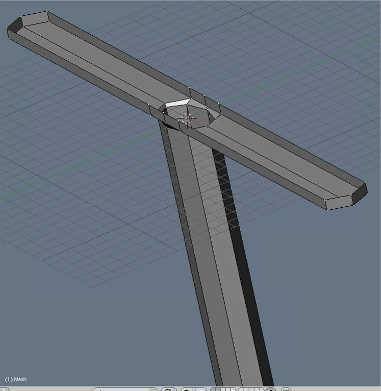
Select (SHIFT+RMB) the two center vertices on either side of the top:
Now in Top View Extrude (EKEY) but don't move them. As soon as you Extrude them, click your LMB to leave them in the same position as the two vertices they were Extruded from. Now you can Scale (SKEY) them down. When you have two vertices selected and then use Scale, they will either be attracted to each other or repelled, depending on which way you move the mouse: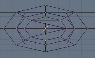
It should give you these two new vertices in Front View: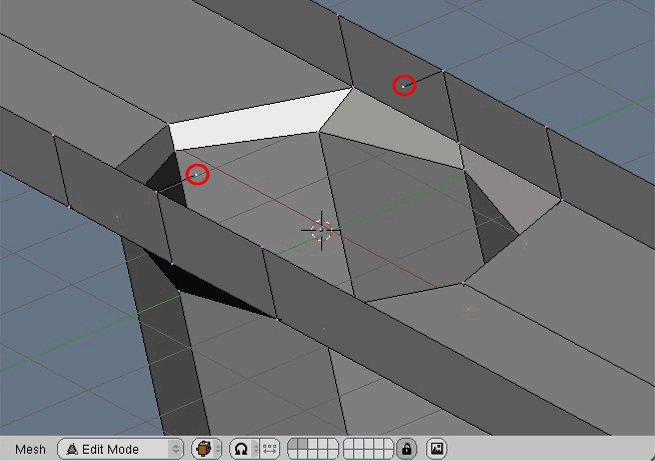
While the new vertices are selected, make a new edge (FKEY) to connect them and then Subdivide (WKEY) to make a vertex in the center of the new edge. The WKEY opens up the Specials menu. Just choose the top option, Subdivide:
Deselect (AKEY) all and Select (RMB) the new center vertex. In Top View move (GKEY) it to the left. Don't forget to use (MMB) to keep it straight. This will be the left side of our blade.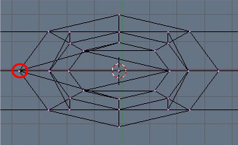
Go back to the left window, which was our Front View that is still Rotated. Deselect (SHIFT+RMB) the vertex we just moved and then Select (SHIFT+RMB) the two vertices that are connected to it: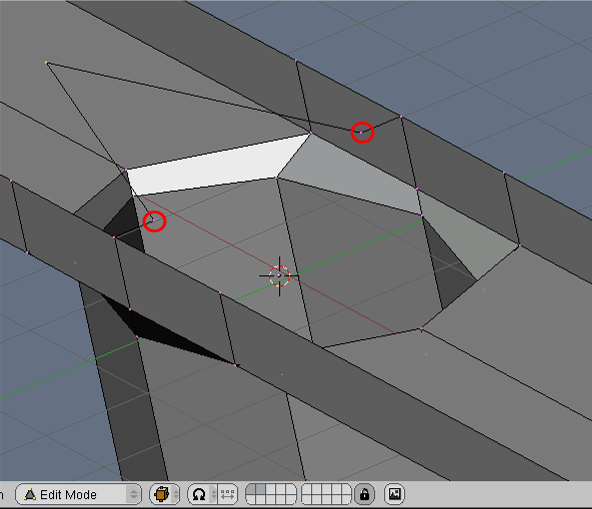
Repeat the process on the right side: (FKEY) for a new edge, (WKEY) to Subdivide it, and Move (GKEY) it out in the Top View:
Select (SHIFT+RMB) the four vertices that make up the diamond shaped base of the blade.
Change the left window back to Front View (NUMPAD 1) and Zoom (MMB) and Pan (SHIFT+MMB) it so that you have room to Extrude (EKEY) the blade straight up:
Now Deselect (AKEY) all vertices and in our Side View Select (RMB) the side vertex at the top of our blade. You should Zoom (MMB) and Pan (SHIFT+MMB) to make this easier. Extrude (EKEY) it up and over. Do not use the (MMB) for this. You do not want to make it follow the axis: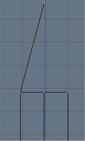
Go back to our Front View and Rotate (MMB) it again. With the top vertex still selected, Select (SHIFT+RMB) the two vertices that make up the left and back points of the blade as shown here:
With the 3 vertices selected we will make a Face (FKEY) out of them
We'll make three more faces to complete the top of the blade. For extra speed, here is a trick I like to use. Since the next face shares 2 vertices with the face we just made, Deselect (SHIFT+RMB) the vertex on the left side and Select (SHIFT+RMB) the vertex on the right side. This is a lot quicker than deselecting all and then re-selecting two of them and a third one. Now make another Face (FKEY):
Repeat my shortcut by Deselecting (SHIFT+RMB) one vertex and Selecting (SHIFT+RMB) the next one in line for a new Face (FKEY). Do this for the remaining two faces:
Switch back to Front View (NUMPAD 1), Deselect (AKEY) all, Select (RMB) and Move (GKEY) the top vertex up or down to make the tip acceptable and then Deselect (AKEY) the vertex:
Now we have to fill in the top of the crosspiece. Let's Pan (SHIFT+MMB), Zoom (MMB), and Rotate (MMB) the Front View to get a good view of the vertices on the front and right side of the blade. Select (SHIFT+RMB) the three vertices circled in red and make a Face (FKEY) with them:
Use the technique that we used on the tip of the sword to fill in the next Face (FKEY):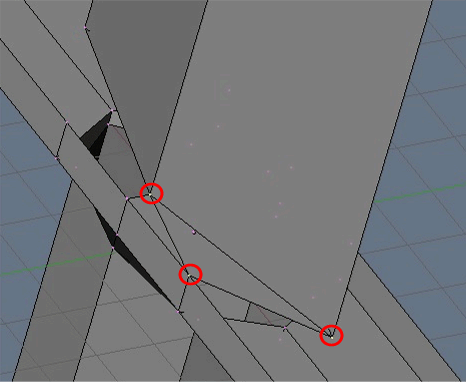
Follow around with the Faces (FKEY) again: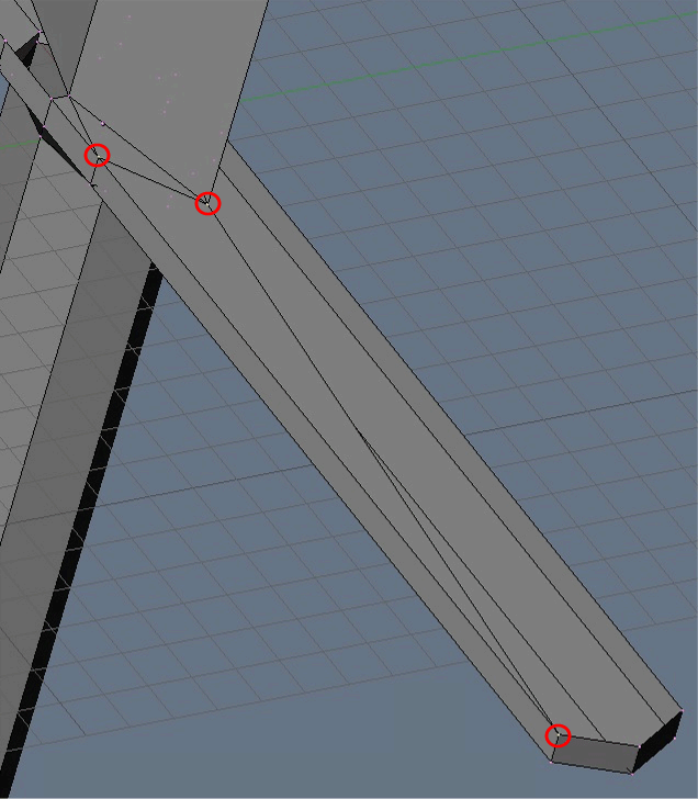
And finally one more Face (FKEY) will round out one-fourth of the crosspiece top: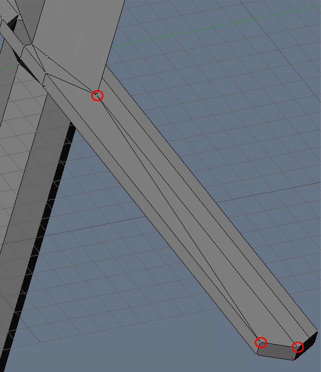
Deselect (AKEY) all and repeat this process three more times to complete the remaining Faces.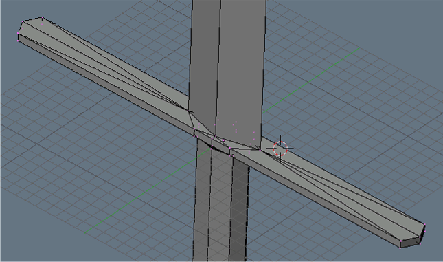
We're almost there. I find it easier to model with quads, but most of you will want your models in triangles. This is a simple matter. Select (AKEY) all of the vertices and use the Triangulate (CTRL+TKEY) to convert any quads into triangles. It will not affect any Faces that are already triangles: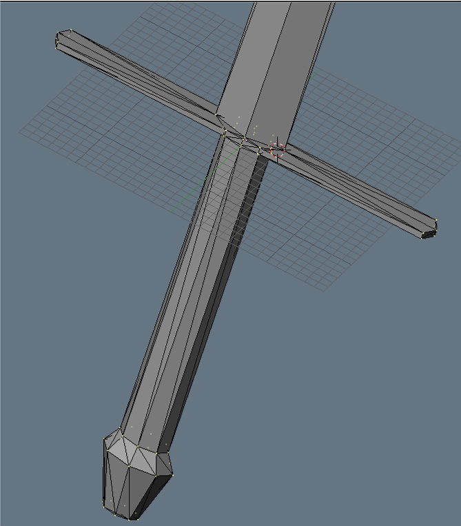
Now we can exit Edit Mode (TAB) and take a look at our sword:
Congratulations, you've made your first Blender sword. It tops out at exactly 130 faces. With today's hardware and some figure models using a few thousand faces, I don't think 130 faces for a sword is too much. But feel free to try and lower it some more. It would actually be a good exercise. You can check the number of vertices and faces on a model at the top of the Blender screen: Next time we will unwrap it, make a texture, and UV map it onto the sword. We will also learn to export it to DirectX. Until then, happy Blending!
--Yoda
Feel free to send me any feedback, questions, or comments [email="yoda@yodasworld.net"]here[/email].


