Date: February 20, 1999
Copyright (C) 1999
[size="5"]Introduction
A few authors recently have discussed methods of alpha blending. For those of you who are clueless as to what alpha blending is, I'd suggest reading some of the other alpha blending tutorials on GameDev.net for a more extensive tutorial. This will be a tough article to work through, and will require a lot of effort on your part to learn everything involved with creating beautiful flares, but the results will be well worth the effort.
[size="5"]Alpha Blending
The basic break-down of the effect is that you create a new color by splitting up two colors, source1 and source2, into their RGB components. You then take percentages of each color component (usually on a 0..255 scale), and add them up to create a destination color component:
Figure 1.
Dest_r = ((source1_r * alpha) + (source2_r * (255-alpha))/255;
 Dest_g = ((source1_g * alpha) + (source2_g * (255-alpha))/255;
 Dest_b = ((source1_b * alpha) + (source2_b * (255-alpha))/255;
When done correctly, you can overlay one semi-translucent image over another image. The next section will assume that you already have at least attempted to perform alpha blending.[size="5"]Alpha Blending Speed-ups
Now if one were to attempt to perform fast alpha blending, you may find that the equations in Figure 1 are not too efficient. Some common speed-ups involve storing the inverse alpha value into a new variable so that it doesn't have to be recalculated each time, ie:
Figure 2.
int inverse_alpha = 255 - alpha;

 Dest_r = ((source1_r * alpha) + (source2_r * inverse_alpha))/255;
 Dest_g = ((source1_g * alpha) + (source2_g * inverse_alpha))/255;
 Dest_b = ((source1_b * alpha) + (source2_b * inverse_alpha))/255;
Well, this gets rid of at least two subtractions. Still not good enough.. we may not even find a fast enough implementation of alpha blending in this article, but we definitely can beat Figure 1. On to new optimizations..Examining Figure 2, we can clearly see that the biggest drawbacks in speed lie in the fact that 6 multiplications and 3 divides are performed. But one thing that really jumps out is the value 255. We won't assume that the compiler optimizes this code in any form and replace the three divides by bit shift operations.
Figure 3.
int inverse_alpha = 255 - alpha;

 Dest_r = ((source1_r * alpha) + (source2_r * inverse_alpha)) >> 8;
 Dest_g = ((source1_g * alpha) + (source2_g * inverse_alpha)) >> 8;
 Dest_b = ((source1_b * alpha) + (source2_b * inverse_alpha)) >> 8;
Ahh, so we've reduced those divides into simple instructions which will execute quite fast. But those 6 muls still jump straight out at us.Here is where things get interesting, we can eliminate at least three multiplications and one subtract instruction by storing our bitmap differently. The rest of these optimizations will apply only to those who don't need to constantly modify their alpha values.
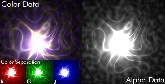
Let's check out some sample data:
Figure 4.
The color data is simply a composite of the red, green, and blue channels. You can see what those channels would look like in the lower left corner of Figure 4. I've added the coloring so it is easier to distinguish between the three channels, but normally they appear in grayscale format. The alpha data represents the level of translucency that the corresponding pixel in the color data should maintain when blitted onto another color surface.
Okay, so here is what we can do. We can use the same amount of space as before with minimal-to-no loss in quality. Simply pre-divide each pixel in the color data by it's corresponding alpha component FIRST.
Figure 5 illustrates how this can be done.
Figure 5.
/*

 In mathematics, you learn something known as an distributive property of real numbers. We can illustrate that property as:

 (A + B) C = AC + BC

 Where A, B, and C are real numbers.

 Now lets see what that looks like in code by expanding the source below :

 */

 int inverse_alpha = 255 - alpha;

 Dest_r = (source1_r * alpha)/255 + (source2_r * inverse_alpha)/255;
 Dest_g = (source1_g * alpha)/255 + (source2_g * inverse_alpha)/255;
 Dest_b = (source1_b * alpha)/255 + (source2_b * inverse_alpha)/255;
As you can see, Figure 5 is virtually identical to Figure 1. We simply store the values (source1_r * alpha)/255, (source1_g * alpha) / 255, and (source2_b * alpha) / 255 in our original bitmap format.Also, our original bitmap format will include some sort of alpha channel. As you can see in the previous code samples, we are only using it in the line:
int inverse_alpha = 255 - alpha;The equation then gets reduced to:
Figure 6.
// Remember that alpha now contains the inverse value (255-alpha)

 Dest_r = source1_r + (source2_r * alpha) >> 8;
 Dest_g = source1_g + (source2_g * alpha) >> 8;
 Dest_b = source1_b + (source2_b * alpha) >> 8;
Are we done yet? For all intents and purposes, yes. I have additional methods of optimization that I haven't tested yet, so I'd prefer not to introduce them at this point in time. Don't forget that you may additionally examine the assembly output of your alpha blending routine, and optimize it by hand.[size="5"]Lens Flare Translucency
Well, I just explained to you everything you'll need to know about alpha blending. Now put that aside, because for lens flares we will utilize additive blending. Blending in this manner is what causes flares to appear purely white over bright surfaces.
Additive blending is done in unoptimized form as follows:
Figure 7.
Dest_r = source1_r + source2_r
 Dest_g = source1_g + source2_g
 Dest_b = source1_b + source2_b

 if (Dest_r > 255) Dest_r = 255;
 if (Dest_g > 255) Dest_g = 255;
 if (Dest_b > 255) Dest_b = 255;
There is an assumption made in the above equation that may cause problems if you try to implement this directly.We assume that Dest_r, Dest_g, and Dest_b are capable of handling numbers greater than 255. One solution could be to leave those values as short 16-bit integers. Though, there may be a better brute-force solution which will allow us to use 8-bit integers and get rid of those nasty "if" statements.
Create a (256+256) byte look-up TABLE as follows:
Figure 8.
unsigned char alut [512];

 for (int i = 0; i < 512; i++)
 {
 alut  = i;
 if (i > 255) alut  = 255;
 }
Here is how the TABLE looks:alut [0] = 0;
alut [1] = 1;
alut [2] = 2;
...
alut [255] = 255;
alut [256] = 255;
...
alut [511] = 255;Figure 9.
Dest_r = alut [source1_r + source2_r];
 Dest_g = alut [source1_g + source2_g];
 Dest_b = alut [source1_b + source2_b];
If anybody finds a more reduced implementation of additive blending, please let me know.I have left out some rather vital information for putting the destination pixel back together, but this can be commonly found in most alpha blending tutorials for various pixel formats.
[size="5"]Parts of a Flare
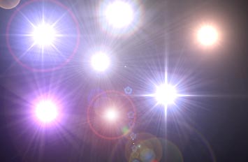
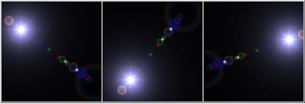
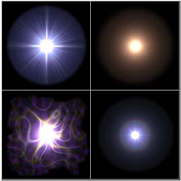
1. Main Flare - The main flare is the most prominent portion of a lens flare. It is what should typically come to mind when you think of lens flares. See below for several examples
The main flare can be broken down into four distinct parts:
2. Secondary Parts
The rest of the flare varies widely between flares. These parts usually appear as small, very translucent, circles.
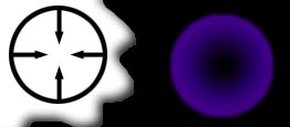
Here, we don't really see too much variation in relation to how the circles are created. The diagram below gives you a basic insight as to how they are created. Generally, you create a ring of any color, and smoothly transition to another color using smaller and smaller rings until your final ring has a radius of 0. Note that you'll need to utilize a blur filter to make it look the most correct.
Figure 11.
The optimal way to create the secondary rings is to create a function which takes at least a radius, an outer ring color, and an inner ring color. You then interpolate the R, G, B values starting from the outer ring color and continuing until you reach the final inner ring color. Looking at figure 11, we could say that the outer ring's color is some shade of purple, while the inner ring color is pure black.
[size="5"]Breaking the Screen Down : Cartesian Coordinates
In order to easily draw lens flares, we'll need to take notice of a property that they all share.
Examine the flare below, and see if you can determine a trend in the positions of the primary flare in relation to the secondary parts of the flare.
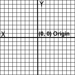
If you haven't noticed yet, all parts of the flare pivot around the center of the image. So as such, we will utilize a coordinate system that is conducive to this sort of pivoting. The Cartesian coordinate system, as demonstrated in figure 10, is perfect for the creation of lens flares because all points are centered around the middle of the graph.
Figure 10.
In order to utilize a Cartesian coordinate system on-screen, we simply set our origin to (X = SCREEN_WIDTH / 2, Y = SCREEN_HEIGHT / 2). We then plot all points on screen in Cartesian coordinates, with the x-extents being +/-(SCREEN_WIDTH / 2) and the y-extents being +/-(SCREEN_HEIGHT / 2).
Converting back to screen coordinates is also easy. We simply add our (X, Y) values for the origin to each (X, Y) pair in Cartesian coordinates.
[size="5"]The Lens Flare Vector
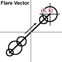
The lens flare we create will have parts that all lie on a straight line. The method that I like to utilize when positioning parts of the lens flare is to set position coordinates only for the main flare using a standard (h, k) center, plotted in cartesian coordinates. All other secondary portions are inverted and/or scaled (h, k) coordinates. While you may use a 2d vector, or a 3d vector if you want the flare to have capabilities of being hidden by geometry (such as a sun behind a star), I find this to be the easiest.
Figure 11.
Remember, (h, k) are simply points in the cartesian coordinate system you set up. They more specifically represent the CENTER of the main flare. The other coordinates are simply scaled and/or inverted h, k coordinates. Note that you can pick out virtually any number to scale the coordinates, and invert any coordinate set as you wish.
What happens when you invert the h, k coordinates is that if your main flare is in the top right corner, the new coordinates would be in the bottom left corner of the screen.
| Main Flare | h | k |
| Secondary Flare | -h | -k |
| Secondary Flare | -h / 2 | -k / 2 |
| Secondary Flare | -h / 1.2 | -k / 1.2 |
| Secondary Flare | h / 3.2 | k / 3.2 |
Screen_coord_x = h + SCREEN_W / 2;
Screen_coord_y = k + SCREEN_H / 2;When blitting the flare portions to the screen using additive blending, don't forget to blit the flare you generate with the new screen coordinates being in the absolute center of the sprite, rather than the top right corner like most blitting functions work.
[size="5"]Using Graphics Programs to Create Flares
Well, we just spent a considerable amount of time talking about how you can graphically generate your very own lens flares. Well, it may not be very practical for most programmers to spend the time writing routines to generate lens flares. So what you need to do is grab a good graphics program like Photoshop and create your own using filters!
Simply render them to a black background and use a crop tool to pick out only the parts you want.
But, for those of you who can't afford an expensive graphics program like Photoshop, I've taken the liberty of creating a few flares for you.
Just click on the flare you like. They are stored in 32-bit TARGA files.
[size="3"]Good Luck!
(C) Copyright 1999, Michael Tanczos.


