Introduction
When
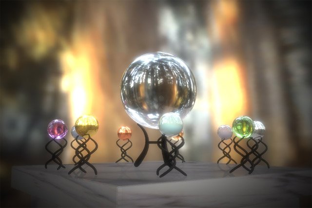
Paul Debevec came up with HDR Rendering in 1998, his revolutionary idea could only be implemented in non-real-time. With the advent of powerful graphics hardware over the past few years, thanks to Moore's law of course, the process can now be implemented on graphics hardware in real-time. Apart from a few demos (including ATI's cool "RNL"), and a couple of articles, there is hardly any info on HDR in real-time. This tutorial is just an introduction that'll help you get your first HDR app running. I won't show you how to make scenes with shiny little spheres on marble tables. What I will teach you is how to load a .hdr file and use it to texture a simple quad, which will then be rendered with "natural light". This tutorial works only on cards that support floating point textures in DX and pixel shaders 2.0, which rules out nVIDIA cards till the Detonator drivers expose floating point textures for DX.
So What is "High Dynamic Range"?
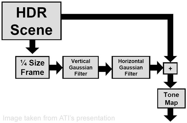
High Dynamic Range is just a neat term for "storing color values much greater than the usual 0.0f to 1.0f used in graphics". Unlike conventional colors used in graphics, where color values cannot exceed 1.0f, the color values here can be anything you like, as high as you like. The advantage of HDR is that your scenes will look more realistic. The process of rendering a scene in HDR is show below :-

- Render the scene with HDR values into a floating point buffer.
- Downsample this buffer to 1/4th size (1/2 width and 1/2 height) and suppress LDR values.
- Run a bloom filter over the downsampled image blurring it along x and y axes.
- Tone map the blurred image after compositing it with the original image. We need to suppress LDR values so that we don't blur those parts of the image. A bloom filter simply bleeds color from one pixel to it's neighboring pixels. We use a Gaussian filter in this case, but you can use any bloom filter.
What are We Waiting For?
Without further ado, let's begin programming our first HDR app. Here I assume that your familiar with DirectX and HLSL and know how to open a window and start a rendering loop. App Variables If you open up the source code (you can find the link at the end of the article), you'll see a lot of global variables. These are used to hold textures and surfaces to render and post-process the scene. You'll also find a couple of effect pointers, which are used to create and handle the HLSL shaders. Apart from these variables, there are a couple of app specific variables like the window handle, vertex structs for the quads, etc... Shown below are the texture and surface pointers which we use as render targets and textures (explained below). ////////////////////////////////////////////////////////////////////// // Global variables ////////////////////////////////////////////////////////////////////// HWND g_hWnd = NULL; // Window handle LPDIRECT3D9 g_pd3d = NULL; // D3D object LPDIRECT3DDEVICE9 g_pd3dDevice = NULL; // D3D device LPDIRECT3DVERTEXBUFFER9 g_pQuadBuffer = NULL; // Quad vertex buffer LPDIRECT3DVERTEXBUFFER9 g_pHalfBuffer = NULL; // Half-screen quad vertex buffer LPDIRECT3DVERTEXBUFFER9 g_pFullBuffer = NULL; // Full-screen quad vertex buffer LPDIRECT3DTEXTURE9 g_pQuadTexture = NULL; // Light probe texture #define FORMAT64 D3DFMT_A16B16G16R16F // Indicates 64-bit format #define FORMAT128 D3DFMT_A32B32G32R32F // Indicates 128-bit format LPDIRECT3DSURFACE9 g_pBackBuffer = NULL; // Pointer to the back buffer LPDIRECT3DTEXTURE9 g_pFullTexture = NULL; // Full screen texture - original // scene is rendered to this LPDIRECT3DSURFACE9 g_pFullSurface = NULL; // Full screen surface LPDIRECT3DTEXTURE9 g_pDownSampleTexture = NULL; // Downsample texture - used // to downsample "FullTexture" LPDIRECT3DSURFACE9 g_pDownSampleSurface = NULL; // Downsample surface LPDIRECT3DTEXTURE9 g_pBlurXTexture = NULL; // Texture used for horizontal blurring LPDIRECT3DSURFACE9 g_pBlurXSurface = NULL; // Corresponding surface LPDIRECT3DTEXTURE9 g_pBlurYTexture = NULL; // Texture used for vertical blurring LPDIRECT3DSURFACE9 g_pBlurYSurface = NULL; // Corresponding surface LPD3DXEFFECT g_pDownSample = NULL; // Effect for Downsample.fx LPD3DXEFFECT g_pBlurX = NULL; // Effect for BlurX.fx LPD3DXEFFECT g_pBlurY = NULL; // Effect for BlurY.fx LPD3DXEFFECT g_pToneMapping = NULL; // Effect for Tonemapping.fx The two vertex structs. #define D3DFVF_QUADVERTEX ( D3DFVF_XYZ | D3DFVF_TEX1 ) // Vertex struct for our 2D quad struct QuadVertex { float x, y, z; float tu, tv; }; #define D3DFVF_SCREENVERTEX ( D3DFVF_XYZRHW | D3DFVF_TEX1 ) // Vertex struct for our "screen-aligned" quad struct ScreenVertex { float x, y, z, rhw; float tu, tv; }; Radiance (.hdr) Format The radiance format is one of the formats that allows you to store floating point images. Paul Debevec has a couple of light probes (just a fancy name for high dynamic range images) on his website. As I said earlier, in this tutorial I show you how to load .hdr files and use them as textures. Since they're in a binary format, to make reading them simpler, I've provided a simple "utility" which I found on the net. It contains some code (rgbe.h and rgbe.cpp) to simplify reading .hdr files. The Actual Process We start off by initializing D3D, creating the device, etc... All this is done in the "init()" function. Now, we need to create 3 vertex arrays. The first called "g_QuadVertices", which is used to render the 2D textured quad into. The second is called "g_HalfVertices", which is used to render the original image into the "downsample render target quad" and the downsampled render target into the "blur target quad", and so on. I chose to call it "g_HalfVertices" because this quad covers 1/4 of the screen (1/2 width and 1/2 height). The final one is called "g_FullVertices", which is used for the "tonemapped render target quad". Then we create corresponding vertex buffers and copy the vertices into them. Next, we have to load our light probe. To do this, we simply read in the array of floats which are actually the RGB components of every pixel in the light probe. Now we need to copy these values to a floating point render target. But to do that, we also need the alpha component since the floating point render target needs 4 components (RGBA). Also, since we're using the 64-bit surface format (D3DFMT_A16B16G16R16F) we need convert the 32-bit floats into 16-bit floats. To do this, we simply use "D3DXFLOAT16" instead of "float". // Read in the HDR light probe. FILE* fp = fopen( "RNL.hdr", "rb" ); rgbe_header_info info; RGBE_ReadHeader( fp, &g_iWidth, &g_iHeight, &info ); // We really don't need this float fExposure = info.exposure; float fGamma = info.gamma; // Create a float array to read in the RGB components float* m_fHDRPixels = new float[3 * g_iWidth * g_iHeight]; memset( m_fHDRPixels, 0, 3 * g_iWidth * g_iHeight * sizeof( float ) ); RGBE_ReadPixels_RLE( fp, m_fHDRPixels, g_iWidth, g_iHeight ); if( FAILED( D3DXCreateTexture( g_pd3dDevice, g_iWidth, g_iHeight, 1, D3DUSAGE_DYNAMIC, FORMAT64, D3DPOOL_DEFAULT, &g_pQuadTexture ) ) ) { MessageBox( g_hWnd, "Unable to create texture", "Error", MB_ICONINFORMATION ); } // Convert the 32-bit floats into 16-bit floats and include the alpha component D3DXFLOAT16* m_fHDR = new D3DXFLOAT16[4 * g_iWidth * g_iHeight]; int j = 0; for( int i = 0; i < 4 * g_iWidth * g_iHeight; i += 4 ) { m_fHDR = m_fHDRPixels[i - j]; m_fHDR[i + 1] = m_fHDRPixels[i + 1 - j]; m_fHDR[i + 2] = m_fHDRPixels[i + 2 - j]; m_fHDR[i + 3] = 0.0f; j++; } // Lock the texture and copy the pixel data into it D3DLOCKED_RECT lr; if(FAILED( g_pQuadTexture->LockRect( 0, &lr, NULL, 0 ) ) ) { MessageBox( g_hWnd, "Unable to lock texture", "Error", MB_ICONERROR ); } memcpy( (D3DXFLOAT16*)lr.pBits, m_fHDR, 4 * g_iWidth * g_iHeight * sizeof( D3DXFLOAT16 ) ); if(FAILED( g_pQuadTexture->UnlockRect( 0 ) ) ) { MessageBox( g_hWnd, "Unable to unlock texture", "Error", MB_ICONERROR ); } delete[] m_fHDRPixels; delete[] m_fHDR; // Set the sampler states g_pd3dDevice->SetSamplerState(0, D3DSAMP_MINFILTER, D3DTEXF_LINEAR); g_pd3dDevice->SetSamplerState(0, D3DSAMP_MAGFILTER, D3DTEXF_LINEAR); Then, we initialize the render targets and create the effects and shaders. void initRTS( void ) { // // Initialize the render targets // D3DXCreateTexture( g_pd3dDevice, 1024, 768, 1, D3DUSAGE_RENDERTARGET, FORMAT64, D3DPOOL_DEFAULT, &g_pFullTexture ); g_pFullTexture->GetSurfaceLevel( 0, &g_pFullSurface ); D3DXCreateTexture( g_pd3dDevice, 512, 384, 1, D3DUSAGE_RENDERTARGET, FORMAT64, D3DPOOL_DEFAULT, &g_pDownSampleTexture ); g_pDownSampleTexture->GetSurfaceLevel( 0, &g_pDownSampleSurface ); D3DXCreateTexture( g_pd3dDevice, 512, 384, 1, D3DUSAGE_RENDERTARGET, FORMAT64, D3DPOOL_DEFAULT, &g_pBlurXTexture ); g_pBlurXTexture->GetSurfaceLevel( 0, &g_pBlurXSurface ); D3DXCreateTexture( g_pd3dDevice, 512, 384, 1, D3DUSAGE_RENDERTARGET, FORMAT64, D3DPOOL_DEFAULT, &g_pBlurYTexture ); g_pBlurYTexture->GetSurfaceLevel( 0, &g_pBlurYSurface ); } void initEffects( void ) { // // Initialize the effects // LPD3DXBUFFER pBuffer; if( FAILED( D3DXCreateEffectFromFile( g_pd3dDevice, "DownSample.fx", NULL, NULL, 0, NULL, &g_pDownSample, &pBuffer ) ) ) { LPVOID pCompileErrors = pBuffer->GetBufferPointer(); MessageBox(NULL, (const char*)pCompileErrors, "Compile Error", MB_OK|MB_ICONEXCLAMATION); PostQuitMessage( 0 ); } if( FAILED( D3DXCreateEffectFromFile( g_pd3dDevice, "BlurX.fx", NULL, NULL, 0, NULL, &g_pBlurX, &pBuffer ) ) ) { LPVOID pCompileErrors = pBuffer->GetBufferPointer(); MessageBox(NULL, (const char*)pCompileErrors, "Compile Error", MB_OK|MB_ICONEXCLAMATION); PostQuitMessage( 0 ); } if( FAILED( D3DXCreateEffectFromFile( g_pd3dDevice, "BlurY.fx", NULL, NULL, 0, NULL, &g_pBlurY, &pBuffer ) ) ) { LPVOID pCompileErrors = pBuffer->GetBufferPointer(); MessageBox(NULL, (const char*)pCompileErrors, "Compile Error", MB_OK|MB_ICONEXCLAMATION); PostQuitMessage( 0 ); } if( FAILED( D3DXCreateEffectFromFile( g_pd3dDevice, "ToneMapping.fx", NULL, NULL, 0, NULL, &g_pToneMapping, &pBuffer ) ) ) { LPVOID pCompileErrors = pBuffer->GetBufferPointer(); MessageBox(NULL, (const char*)pCompileErrors, "Compile Error", MB_OK|MB_ICONEXCLAMATION); PostQuitMessage( 0 ); } } The "setupEffectParams()" function contains functions to set up shader parameters and is called before rendering each "effect". void setEffectParams( void ) { // // Setup the effect parameters // D3DXMATRIX matMVP = g_matWorld * g_matView * g_matProj; D3DXMatrixTranspose( &matMVP, &matMVP ); g_pDownSample->SetMatrix( "matMVP", &matMVP ); g_pDownSample->SetTexture( "tDownSample", g_pFullTexture ); g_pBlurX->SetMatrix( "matMVP", &matMVP ); g_pBlurX->SetTexture( "tBlurX", g_pDownSampleTexture ); g_pBlurY->SetMatrix( "matMVP", &matMVP ); g_pBlurY->SetTexture( "tBlurY", g_pBlurXTexture ); g_pToneMapping->SetMatrix( "matMVP", &matMVP ); g_pToneMapping->SetTexture( "tFull", g_pFullTexture ); g_pToneMapping->SetTexture( "tBlur", g_pBlurYTexture ); if( g_bVaryExposure ) { if( g_fExposureLevel < 0.0f ) g_fExposureLevel += 0.01f; else if( g_fExposureLevel > 0.0f && g_fExposureLevel <= 10.0f ) g_fExposureLevel += 0.01f; else if( g_fExposureLevel > 10.0f ) g_fExposureLevel = 0.01f; } g_pToneMapping->SetFloat( "fExposureLevel", g_fExposureLevel ); } The rendering process is very simple. - Render the scene to a floating point render target
- Downsample that render target and suppress LDR values
- Take the downsampled target and blur it horizontally
- Blur this vertically
- Tone map the original and blurred targets to get a displayable image So, now we get to the interesting part, how things exactly work. We begin by rendering the textured "quad vertices" into a floating point render target. Now, we need to downsample this to 1/4th its size, suppressing the LDR values, so that we don't blur the entire scene. To do this, we simply use the original render target as a texture and render this onto another render target 1/4th the "original" size. To suppress the LDR values, the below function "SuppressLDR" is used. Kd is the material's diffuse color. Downsample.fx
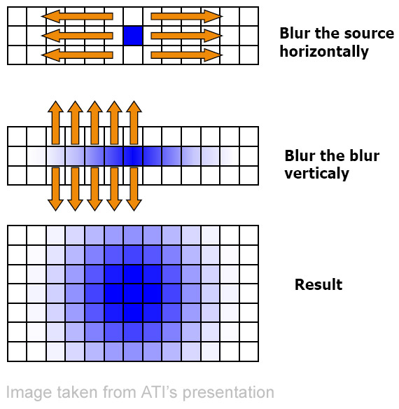
////////////////////////////////////////////////////////////////////// // Vertex shader ////////////////////////////////////////////////////////////////////// struct VS_OUT { float4 Pos: POSITION; float2 Tex: TEXCOORD0; }; VS_OUT vs_main( float3 inPos: POSITION, float2 inTex: TEXCOORD0 ) { VS_OUT OUT; // Output the transformed vertex OUT.Pos = mul( matMVP, float4( inPos, 1 ) ); // Output the texture coordinates OUT.Tex = inTex + ( PixelOffset * 0.5 ); return OUT; } ////////////////////////////////////////////////////////////////////// // Pixel shader ////////////////////////////////////////////////////////////////////// float4 SuppressLDR( float4 c ) { if( c.r > 1.0f || c.g > 1.0f || c.b > 1.0f ) return c; else return float4( 0.0f, 0.0f, 0.0f, 0.0f ); } float4 ps_main( float2 inTex: TEXCOORD0 ) : COLOR0 { float4 color = tex2D( DownSampler, inTex ) * Kd; return SuppressLDR( color ); } Next, we need to blur the downsampled image in order to "bleed" colors from the bright pixels into neighboring pixels. To do this, as mentioned earlier, we use a separable Gaussian filter. In the first pass, we blur pixels along the x-axis, we then take this image and blur it along the y-axis. Pretty simple, huh? The below code fragment is from BlurX.fx. BlurX.fx ////////////////////////////////////////////////////////////////////// // Vertex shader ////////////////////////////////////////////////////////////////////// struct VS_OUT { float4 Pos: POSITION; float2 Tex: TEXCOORD0; }; VS_OUT vs_main( float3 inPos: POSITION, float2 inTex: TEXCOORD0 ) { VS_OUT OUT; // Output the transformed vertex OUT.Pos = mul( matMVP, float4( inPos, 1 ) ); // Output the texture coordinates OUT.Tex = inTex + ( PixelOffset * 0.5 ); return OUT; } ////////////////////////////////////////////////////////////////////// // Pixel shader ////////////////////////////////////////////////////////////////////// float4 ps_main( float2 inTex: TEXCOORD0 ) : COLOR0 { float4 color = tex2D( BlurXSampler, inTex ); // Sample pixels on either side for( int i = 0; i < 8; ++i ) { color += tex2D( BlurXSampler, inTex + ( BlurOffset * i ) ) * PixelWeight; color += tex2D( BlurXSampler, inTex - ( BlurOffset * i ) ) * PixelWeight; } return color; } We just create a loop that adds weighted neighboring pixels. We sample 8 pixels from either side. BlurOffset is actually the per-pixel (or texel) width, and we multiply it by the iteration number "i" to get the coordinates of the "i"th pixel.  Blurring along the y-axis is the same, only we provide the per pixel height this time. Now comes the most important part, compositing the original and blurred images and tone mapping them to get a displayable image. The below code sample is from ToneMapping.fx, which shows how to combine the 2 images. Tonemapping.fx
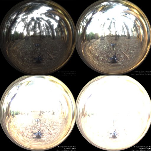
 ////////////////////////////////////////////////////////////////////// // Vertex shader ////////////////////////////////////////////////////////////////////// struct VS_OUT { float4 Pos: POSITION; float2 Tex: TEXCOORD0; }; VS_OUT vs_main( float3 inPos: POSITION, float2 inTex: TEXCOORD0 ) { VS_OUT OUT; // Output the transformed vertex OUT.Pos = mul( matMVP, float4( inPos, 1 ) ); // Output the texture coordinates OUT.Tex = inTex + ( PixelOffset * 0.5 ); return OUT; } ////////////////////////////////////////////////////////////////////// // Pixel shader ////////////////////////////////////////////////////////////////////// float4 ps_main( float2 inTex: TEXCOORD0 ) : COLOR0 { float4 original = tex2D( FullSampler, inTex ); float4 blur = tex2D( BlurSampler, inTex ); float4 color = lerp( original, blur, 0.4f ); inTex -= 0.5; float vignette = 1 - dot( inTex, inTex ); color *= pow( vignette, 4.0 ); color *= fExposureLevel; return pow( color, 0.55 ); } First, we simply lerp between the original and blurred colors. Then, we calculate the vignette (which is the square of the distance of the current pixel from the center of the screen) and multiply the lerped color by vignette raised to the fourth power. Finally, we multiply by the exposure level, which determines how "exposed" your finally image should be, just like you can set the exposure in a camera, and add a gamma correction.  Shown above are images of the light probe at different exposures. Left-Top - Under exposed (0.5) Right-Top - Properly exposed (2.5) Left-Bottom - Over exposed (10.0) Right-Bottom - Extremely over exposed (20.0) To properly observe "glow" effects, you'll need either the grace-cube texture or the grace light probe from www.debevec.org. Voila! Your first HDR app is done. This may not be the most efficient way to do things, since I only wanted to show the basics. So I leave the optimizing part to you. Masaki Kawase has implemented a different method for post-processing, and after implementing it I found out that it actually gives better performance, albeit not the same quality. There are other types of glows, like star, afterimage, etc... which I didn't discuss. You could try and implement them as well. Now let's see if your game comes out with HDR Rendering before Half-Life 2 does! If you have any doubts, questions or suggestions, you can mail me at [email="anidex@yahoo.com"]anidex@yahoo.com[/email]. Here is the source code RNL.zip.
 References
- Real-Time 3D Scene Post-processing. Jason L. Mitchell.
- DirectX(R)9 Shading. Jason L. Mitchell.
- Frame Buffer Post-processing Effects in DOUBLE-S.T.E.A.L (Wreckless). Masaki Kawase.
- Light probes courtesy of www.debevec.org.


