As the information available on Direct3D is quite a lot, we will present the information on Direct3D using three tutorials, with each covering a different aspect of Direct3D. The three tutorials are:
- Overview of Direct3D
- Direct3D Retained Mode
- Direct3D Immediate Mode
[size="5"]DirectX
DirectX is a set of APIs, available as COM (Component Object Model) objects. These APIs provide objects and functions for developing real-time, high-performance applications on the Windows platform.
The primary motivation for developing these libraries is that the performance of existing Windows applications catering to graphics intensive application like games and multimedia is very poor in comparison to the same applications developed on DOS. The DirectX set has been developed keeping this need for high performance in mind, and it provides a standard, robust platform for developing such applications.
DirectX provides a standard, robust platform to application developers, by guaranteeing hardware independence. This is done by providing a consistent interface to the hardware. Due to this, the complexity of software development is reduced and the incompatibilities between the hardware platforms is neutralized as far as possible. The present applications, written in DOS, have to take care of the different hardware configurations, making them quite configuration specific and harder to port to different configurations. By providing a consistent interface across all hardware platforms, taking care of incompatibilities is shifted away from the application developer, resulting in less code and hence faster development.
Hardware independence is guaranteed by DirectX, by providing requirement guidelines to all hardware vendors. Due to these guidelines, it is ensured that at least minimal support is guaranteed to the applications.
DirectX is not a single entity, but a collection of closely interacting and interdependent applications. The components of DirectX are:
DirectDraw
[bquote]- for 2D interactions, like fast 2D blitting (bit block transfers), overlays, etc[/bquote] DirectSound
[bquote]- for incorporating soung into applications [/bquote]DirectPlay
[bquote]- for incorporating multiple users into the applications, using the network for communicating between the users[/bquote] Direct3D
[bquote]- for incorporating 3D capabilities into applications [/bquote]DirectInput
[bquote]- for incorporating support for other peripherals, like joysticks, into the applications[/bquote] Of these components, let us briefly cover the DirectDraw component, before covering the overview of Direct3D.
[size="5"]DirectDraw
The DirectDraw component is important, as many of its features are used either directly or indirectly by the Direct3D component of DirectX.
The DirectDraw component is implemented in hardware and software. DirectDraw is the only client of the DirectDraw hardware abstraction layer (HAL). The HAL protects the application from the differences of the different hardware. Applications using DirectDraw only communicate with DirectDraw and cannot access the HAL directly or indirectly.
DirectDraw improves performance by providing support for 2D functions of the applications. It provides direct access to the off screen bitmaps, making access faster.
It also provides fast access to a blitting (bit block transfer) and buffer flipping. Some of the other features include support for transparent blitting and support for overlays, for implementing sprites and managing multiple layers of animation.
All these features help in drastically improving the performance of the Windows applications as compared to Windows applications written without such support.
[size="5"]DirectDraw Objects
An application using DirectDraw, uses two objects, namely DirectDraw and DirectDrawSurface. The DirectDraw object represents the display adapter card. The DirectDrawSufrace object represents the display memory, on which the data to be displayed is rendered.
Applications can also make use of additional objects like DirectDrawPalette and DirectDrawClipper.
[size="5"]Common Usage
A standard method of using DirectDraw is given below:
- Create the front buffer and back buffer (to exchange the images)
- Images to be displayed are written to the back buffer, instead of directly to the screen
- At the end of drawing, the screen is updated by flipping the back and the front buffers. After this flipping operation, the back buffer becomes the current front buffer while the front buffer becomes the current back buffer
[size="5"]Direct3D
After taking a brief look at the capabilities of DirectDraw, let us come to the overview of Direct3D.
[size="3"]Introduction
Direct3D, is part of DirectX and is the component that helps us integrate 3D into Windows applications. Direct3D is used to develop real-time, interactive, 3D applications.
For developing these applications, Direct3D provides the following features:
Device independence
[bquote]- helps shield the applications from the vagaries of the different hardware platforms. As a result of this, applications become independent of the hardware platform and hence become more portable [/bquote]Common driver model to hardware
[bquote]- guarantees to applications, that all the drivers supporting Direct3D will support a defined minimal set of features and capabilities. Due to this, applications developed using such features will work on all hardware platforms. Additionally, Direct3D provides a specification to all hardware developers, which help their cards support the various Direct3D features. Applications using these features will see a boost in performance[/bquote] Eases addition of 3D to applications
[bquote]- as Direct3D provides a standard mechanism and a standard set of algorithms for 3D graphics, applications requiring such features can be developed much faster. Additionally, the time spent in developing such well known and well defined techniques is saved, helping in developing applications faster[/bquote] Transparent access to hardware acceleration
[bquote]- is one of the very important features of Direct3D, which uses the hardware support, if available. In case a hardware platform does not support a certain feature, Direct3D provides an equivalent implementation in software. This choice of using the hardware features if available, is transparent to the user. The application, at runtime can detect the hardware capabilities and use them if present [/bquote] In addition to these features, Direct3D provides a fast software based rendering of the full 3D rendering pipeline. Applications developed using Direct3D are scalable as a part or whole of the 3D rendering pipeline can be in the hardware and Direct3D can make use of it, if it is detected.
A possible restriction on Direct3D is the tight restriction with DirectX and its different components.
The features of Direct3D are available to the user in two different ways. These are through the two modes of Direct3D, namely: the retained mode and the immediate mode. The retained mode is a high-level interface, while the immediate mode is a lower-level interface to the features of Direct3D. The two modes are discussed in details in separate tutorials. For detailed discussions of the retained mode and the immediate mode, refer [8] and [7] respectively.
[size="3"]Place
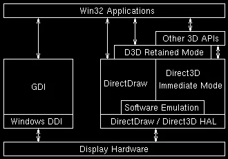
Figure 1 shows the different parts of Direct3D, in relation to the other modules of a Win32 system.
From figure 1, it is clear that the retained mode uses the immediate mode, transparent to the developer using the retained mode. The developer is not made aware of this usage. From the figure, it is also clear that the retained mode also uses some features of DirectDraw. The retained mode, the immediate mode and the Direct3D HAL, together, constitute the Direct3D component of DirectX.
Though many of the existing programs for 3D graphics on the Windows platform talk to the different parts directly, it is envisaged that the DirectDraw and Direct3D components of DirectX will be incorporated into future versions of Win32 systems. Any system providing 3D, will have to use Direct3D to provide its own features.
[size="3"]Layers
Direct3D uses two layers, namely the Hardware Abstraction Layer (HAL) and the Hardware Emulation Layer (HEL).
All of the features of Direct3D are built on top of the HAL, which provides hardware independence and makes applications portable.
The HEL is a companion of Direct3D and provides software emulation for the features of the 3D rendering pipeline, not supported by the hardware. This layer is tightly integrated with the DirectDraw HAL and the Graphics Device Interface (GDI) driver of the Win32 system. This layer helps provide a unified driver model for accelerated 3D.
[size="5"]Rendering Engine
The rendering engine forms an important part of Direct3D. It is responsible for taking a scene definition in terms of points in 3D, the different texture specifications, the lights and the camera specifications, and rendering ready, so that it can be displayed on the display device.
The functionality of the rendering engine is provided using three modules, namely the transformation module, the lighting module and the rasterization module. Each of these modules can be hardware accelerated, transparent to the user of the application. The application developer only has to put the detection facility into the application, which will allow it to query the hardware to find and use its capabilities, if present.
Figure 2 shows the three modules of the rendering engine and their interactions with the Direct3D API, before displaying the results on the rendering target, which is the 2D display surface. The diagram shows the sequence of operations performed on the data, before it is displayed.
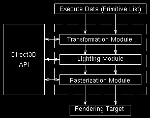
Figure 2: Rendering Engine Modules
The 3D data to be displayed, is given to the transformation module, which maps the 3D data onto its equivalent 2D data. This 2D data is then given to the lighting module, which calculates the light received by the data, considering the lights in the scene. The lit data is then given to the rasterization module, which calculates the transparency and applies the texture to the data. After rasterization, the data is 2D, lit using the different lights in the scene and may also have the specified texture maps applied to them.
Let us now consider each of the modules in a bit more detail.
[size="3"]Transformation Module
The transformation module is the first of the three modules of the rendering engine. This module handles the geometry transformations in the rendering engine. To do this, it uses three four-by-four (4x4) matrices, namely the view transformation matrix, the world transformation matrix and the projection matrix. For an explanation of these three matrices, refer [5], [6], [11], [12], [13] and [14]. The three matrices are maintained in three state registers, namely the viewing matrix, the world matrix and the projection matrix, respectively. This module uses one more state register, the viewport, for holding the dimensions of the 2D display area.
The transformation module combines all the matrices into one composite matrix and uses this for computations, as using only one matrix, as opposed to four, speeds up the calculations in the application.
It is possible to set the states of the state registers separately, in addition to setting the value of the composite matrix. But, it is advisable to let Direct3D calculate the composite matrix, as the matrix multiplication operations required, have been specially optimized in Direct3D. Additionally, the newer versions of DirectX make use of MMX technology.
Figure 3 shows a diagrammatic representation of the transformation module.
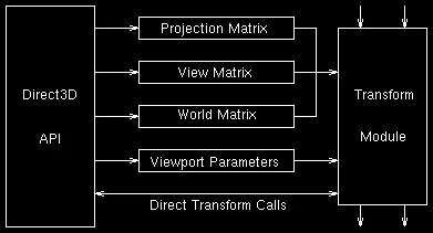
Figure 3: Transformation Module
[size="3"]Lighting Module
The lighting module of the rendering engine is the second of the three modules. It uses the data provided by the transformation module and calculates the lighting information for the received data.
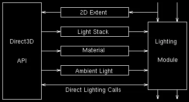
This module maintains a stack of the current lights and the ambient light level and the different material properties of the data. All this information is used while calculating the light falling at a particular point in the scene.
Figure 4 shows a diagrammatic representation of the lighting module.
The lighting module can be operated in any one of the two lighting models it supports. The two models supported are:
Monochromatic model
[bquote]- also known as the ramp model. This model uses only the gray component of each light source specified in the scene, to calculate a single shade value. This shade value is the diffuse component. Though this model supports multiple light sources, the colour components of the lights are ignored.
A restriction of this model is that only gray shades can be displayed and the textures used have to be of 8-bit depth. An advantage of this model over the RGB model is that it gives better performance than the RGB model.[/bquote] RGB model
[bquote]- is the other model supported by the lighting module of the rendering engine. This model helps produce more realistic effects of the given scene, as it uses the full colour content of the light sources and the material of the object being lit. This model supports multiple coloured light sources.
A limitation of this model is that it may produce a banding effect if the colour depth available is not very good. In the banding effect, the transition from one colour to another, is not smooth. It is as if two different coloured bands have been placed side-by-side. This effect is produced when the number of pixels available for representing the colours is far less than the number of colours actually required by the application to display the data properly. Also, its performance as compared to the monochromatic model may be less[/bquote][size="3"]Rasterization Module
The rasterization module is the last of the three modules of the rendering engine. This module takes only execute calls and the data and displays it onto the display surface.
On being given the execute call, the module goes through the list of vertices to be displayed and generates the transfomed vertices to be rendered. Clipping parameters can also be specified in this module. The module also culls back-facing triangles, viz. the triangles whose surface normals face away from the camera. An important point about this module is that it renders only clockwise oriented triangles.
Figure 5 shows a diagrammatic representation of the rasterization module.
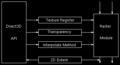
Figure 5: Rasterization Module
For more details on the Direct3D API and its features, refer [3] and [2].
[size="5"]File Format
Though we have said until now that Direct3D can be used to display 3D data and though it is possible to generate 3D data on the fly, it is very difficult and restrictive to store information of various complex models and scenes, typically used in 3D systems, directly inside the application. Usually, a 3D scene is specified using a data file, which provides all the relevant information required for rendering purposes.
Though Direct3D does not provide a file format for specifying whole scenes, it provides a file format to specify a 3D mesh object that can be placed in a scene.
This file format is template driven and is architecture neutral and context free. It is also extensible and new templates can be added very easily. The file format allows storage of predefined object meshes, texture and animations, in addition to allows storage of user defined objects. Applications can define higher-level templates using existing lower-level or other higher-level templates.
The file format is the DirectX file format and has a ``.x'' extension. It is also called the ``xof'' file. This file format is natively supported and used by the retained mode, which provides objects and methods to read, save and manipulate a file.
The file format allows specification of fixed path animations and also supports instancing of objects, which helps in reuse of data sets and hence reducing the total size of the object being manipulated.
Let us now consider the details of the file format.
A data file can be split into three parts, namely: header, template and data. Each of the parts is described in the following sections.
[size="3"]Header
The header part contains information which helps identify the file. It is compulsory at the beginning of the file. The header consists of a magic number (``xof''), which identifies the file and the major and minor version numbers of the file. These numbers can be used to take care of versioning problems in data files, if required.
The version numbers are followed by the format type, which can be one of the following:
- ``txt'' - text file
- ``bin'' - binary file
- ``com'' - compressed file If the file is a compressed file, the compression type is specified following the format type. The compression type can be one of the following:
- ``lzw'' - LZW compression algorithm
- ``zip'' The compression type is followed by 4 digits, which indicate the number of bits used to represent floating point numbers.
[size="3"]Template
The different templates used in the file follow the header information. A template defines how a data stream is to be interpreted by the reader of the file.
A template is specified using a skeleton, as shown in figure 6.template{
. . . .
[restrictions]
}
Figure 6: Template Specification Skeleton
A template has a name, which is used to identify the data type being read, when it is encountered. The name is followed by the UUID (Universally Unique IDentifier) of the COM object to be used to read this template when it is encountered. The UUID is followed by a list of members of the template. The member list can be followed by an optional list of restrictions that need to be observed while reading the data or creating the data structure to hold the read data.
[size="3"]Data
This part contains the actual object information. The data part can either store actual data or a reference to the data. This referencing is used for the feature of instancing, supported by the file format. The feature of instancing allows reference to an data set, if it is required at multiple places, instead of replicating all the data elements. Each data object is read using a corresponding template object. All data objects have to belong to one of the templates specified after the header.
The data is specified using a template skeleton, as illustrated in figure 7.[name] {
. . . .
}Figure 7: Data Format Skeleton
[size="3"]Sample Data File
A sample data file, to help understand the file format is presented in appendix A.
[size="5"]DirectX and COM
Before we conclude the overview on Direct3D, we would like to briefly comment in the relationship between DirectX and the Component Object Model (COM), and its usage.
DirectX is based on the principles of COM, which allow us to develop and distribute the required functionality, packaged as components or objects. Most of the objects and interfaces in DirectX are based on COM and many of the DirectX APIs are instantiated as a set of OLE objects.
[size="3"]COM Interface
All the functions supported by a COM object are available as interfaces of that object. An interface is nothing but a group of related functions. The user of a component has to query the component for an interface. If an interface is supported by an object, a reference is returned, which in turn can be used to access the different methods provided in the interface.
[size="3"]IUnknown
To allow a component user to query for an interface, all COM objects have to be derived from the standard IUnknown interface. This interface provides three methods, namely AddRef, QueryInterface and Release.
[size="3"]AddRef
All COM objects work on the principle of reference counting. Whenever a COM object is used, its reference count is incremented by one. The reference count is decremented by one, when the object is released, using the Release method. An object is a valid candidate for garbage collection, when its reference count becomes zero.
[size="3"]QueryInterface
This method is used to query an object for its supported interface and hence the supported methods. The supported features can be accessed by asking for a specific interface from the COM object. If the interface is supported, QueryInterface returns a pointer to the interface and calls AddRef to increment the reference count on the COM object. It is the responsibility of the application to call Release, after its work with the COM object is over. After getting a pointer to the interface, the application can call specific methods from the interface, to get its job done.
Typically, DirectX provides one object per device.
[size="3"]COM Advantage
An advantage that we get by using COM is that we can have language independence between the COM object and its users. What this means is that a COM object can be used irrespective of the language being used for developing the application requiring 3D capabilities.
Though many languages can be used with COM objects the languages we briefly cover are the C programming language and the C++ programming language. We are considering these two languages as they are the part of the primary languages being used to develop applications and that the differences between using these languages though not being very major, are significant. Using these languages does not change the way we use COM objects for incorporating 3D content into our applications. Another motivating factor for choosing these two languages is the comfort level of the authors, in using these languages.
For more details on COM and its usage with other languages, refer [1].
[size="3"]C++ and COM
Code written C++ and COM is less complex that equivalent code written in C and COM. In C++, a COM interface is like an abstract base class, with all methods being pure virtual. Both C++ and COM use virtual tables (vtable) for pure virtual functions.
When COM objects are used through C++, the QueryInterface method returns a pointer to the virtual table and the different methods supported by the object can be accessed directly.
The sample in source listing 1 illustrates the usage of COM objects through C++.In this sample, the QueryInterface method is being invoked for us by the Direct3DRMCreate function. This function returns a pointer to the Direct3DRM (Direct3D Retained Mode) object, which provides different methods like creation of a viewport, loading a mesh, etc. Notice that we are not calling the AddRef explicitly, but we are calling the Release method, after using the COM object.LPDIRECT3DRM lpD3DRM; // Direct3D object
LPDIRECT3DRMDEVICE dev; // Direct3DRM device
// viewport through which the scene is viewed
LPDIRECT3DRMVIEWPORT view;
LPDIRECT3DRMFRAME camera; // camera
. . .
. . .
Direct3DRMCreate(&lpD3DRM);
. . .
. . .
lpD3DRM->CreateViewport(device, camera,
0, 0, width, height, &view);
. . .
. . .
view->Release();
[size="3"]C and COM
A major difference between using C and C++ and COM is that the QueryInterface method does no return a pointer to the virtual table, when COM objects are used through C. The methods of the COM object have to be explicitly invoked through the virtual table as is illustrated in the sample code in source listing 2.Note the explicit use of the pointer to the virtual table lpVtbl and passing of the object itself as the first parameter in each method call.// The methods of the COM object have to be explicitly invoked through
// the virtual table as is illustrated below
LPDIRECT3DRM lpD3DRM; // Direct3D object
LPDIRECT3DRMDEVICE dev; // Direct3DRM device
// viewport through which the scene is viewed
LPDIRECT3DRMVIEWPORT view;
LPDIRECT3DRMFRAME camera; // camera
. . .
. . .
Direct3DRMCreate(&lpD3DRM);
. . .
. . .
lpD3DRM->lpVtbl->CreateViewport(lpD3DRM, device,
camera, 0, 0, width, height, &view);
. . .
. . .
view->lpVtbl->Release(view);
A few points to be remembered while using COM objects through C are:- The first parameter of each method call on an object, has to refer to the object on which the methods is being invoked
- Each method of an object has to be explicitly accessed through the pointer to the virtual table (lpVtbl) [size="3"]Notes on Programming
For developing applications using Direct3D on Windows, knowledge of Windows programming using the SDK or MFC is necessary. For more details on programming using SDK and using MFC, refer [9] and [10] respectively.
[size="5"]Summary
In this tutorial, we have seen that Direct3D is one of the components of DirectX and is an API for 3D graphics programming. This API gives hardware independence in addition to transparent hardware acceleration and a fast software based emulation for missing hardware implementations of the rendering pipeline. We saw that the rendering engine of Direct3D consists of three modules, namely the transformation module, the lighting module and the rasterization module. We mentioned the different modes in which Direct3D can be operated, namely the retained mode and the immediate mode.
Then we covered the file format used to represent the data objects and the relationship of Direct3D to COM and its usage in the C++ and C programming languages.
[size="3"]Appendix A
This section presents a sample data file. The data file specifies a cube.[size="3"]References// Appendix A - This section presents a sample data file.
// The data file specifies a cube
xof 0302txt 0064
template Header {
<3D82AB43-62DA-11cf-AB39-0020AF71E433>
WORD major;
WORD minor;
DWORD flags;
}
template Vector {
<3D82AB5E-62DA-11cf-AB39-0020AF71E433>
FLOAT x;
FLOAT y;
FLOAT z;
}
template Coords2d {
FLOAT u;
FLOAT v;
}
template Matrix4x4 {
array FLOAT matrix[16];
}
template ColorRGBA {
<35FF44E0-6C7C-11cf-8F52-0040333594A3>
FLOAT red;
FLOAT green;
FLOAT blue;
FLOAT alpha;
}
template ColorRGB {
FLOAT red;
FLOAT green;
FLOAT blue;
}
template IndexedColor {
<1630B820-7842-11cf-8F52-0040333594A3>
DWORD index;
ColorRGBA indexColor;
}
template Boolean {
<4885AE61-78E8-11cf-8F52-0040333594A3>
WORD truefalse;
}
template Boolean2d {
<4885AE63-78E8-11cf-8F52-0040333594A3>
Boolean u;
Boolean v;
}
template MaterialWrap {
<4885AE60-78E8-11cf-8F52-0040333594A3>
Boolean u;
Boolean v;
}
template TextureFilename {
STRING filename;
}
template Material {
<3D82AB4D-62DA-11cf-AB39-0020AF71E433>
ColorRGBA faceColor;
FLOAT power;
ColorRGB specularColor;
ColorRGB emissiveColor;
[...]
}
template MeshFace {
<3D82AB5F-62DA-11cf-AB39-0020AF71E433>
DWORD nFaceVertexIndices;
array DWORD faceVertexIndices[nFaceVertexIndices];
}
template MeshFaceWraps {
<4885AE62-78E8-11cf-8F52-0040333594A3>
DWORD nFaceWrapValues;
Boolean2d faceWrapValues;
}
template MeshTextureCoords {
DWORD nTextureCoords;
array Coords2d textureCoords[nTextureCoords];
}
template MeshMaterialList {
DWORD nMaterials;
DWORD nFaceIndexes;
array DWORD faceIndexes[nFaceIndexes];
[Material]
}
template MeshNormals {
DWORD nNormals;
array Vector normals[nNormals];
DWORD nFaceNormals;
array MeshFace faceNormals[nFaceNormals];
}
template MeshVertexColors {
<1630B821-7842-11cf-8F52-0040333594A3>
DWORD nVertexColors;
array IndexedColor vertexColors[nVertexColors];
}
template Mesh {
<3D82AB44-62DA-11cf-AB39-0020AF71E433>
DWORD nVertices;
array Vector vertices[nVertices];
DWORD nFaces;
array MeshFace faces[nFaces];
[...]
}
template FrameTransformMatrix {
Matrix4x4 frameMatrix;
}
template Frame {
<3D82AB46-62DA-11cf-AB39-0020AF71E433>
[...]
}
Header {
1;
0;
1;
}
Material x3ds_mat_GREEN_0_ {
0.000000, 0.666667, 0.000000, 1.000000;;
15.000000;
0.874510, 1.000000, 0.839216;;
0.00, 0.00, 0.00;;
}
Frame x3ds_cube {
Mesh cube {
8;
-40.000000; -30.000000; -49.999996;,
40.000000; -30.000000; -49.999996;,
40.000000; 29.999998; -50.000000;,
-40.000000; 29.999998; -50.000000;,
-40.000000; -30.000000; 50.000000;,
40.000000; -30.000000; 50.000000;,
40.000000; 30.000000; 50.000000;,
-40.000000; 30.000000; 50.000000;;
12;
3;0,2,1;,
3;0,3,2;,
3;0,5,4;,
3;0,1,5;,
3;1,6,5;,
3;1,2,6;,
3;2,7,6;,
3;2,3,7;,
3;3,4,7;,
3;3,0,4;,
3;4,6,7;,
3;4,5,6;;
MeshMaterialList {
1;
12;
0,
0,
0,
0,
0,
0,
0,
0,
0,
0,
0,
0;
{x3ds_mat_GREEN_0_}
}
MeshNormals {
24;
0.000000;-0.000000;-1.000000;,
0.000000;-1.000000;0.000000;,
-1.000000;0.000000;0.000000;,
0.000000;-0.000000;-1.000000;,
0.000000;-1.000000;0.000000;,
1.000000;0.000000;0.000000;,
0.000000;-0.000000;-1.000000;,
1.000000;0.000000;0.000000;,
-0.000000;1.000000;-0.000000;,
0.000000;-0.000000;-1.000000;,
0.000000;1.000000;-0.000000;,
-1.000000;0.000000;0.000000;,
0.000000;-1.000000;0.000000;,
-1.000000;0.000000;0.000000;,
0.000000;0.000000;1.000000;,
0.000000;-1.000000;0.000000;,
1.000000;0.000000;0.000000;,
0.000000;0.000000;1.000000;,
1.000000;0.000000;0.000000;,
-0.000000;1.000000;-0.000000;,
0.000000;0.000000;1.000000;,
-0.000000;1.000000;-0.000000;,
-1.000000;0.000000;0.000000;,
0.000000;0.000000;1.000000;;
12;
3;0,6,3;,
3;0,9,6;,
3;1,15,12;,
3;1,4,15;,
3;5,18,16;,
3;5,7,18;,
3;8,21,19;,
3;8,10,21;,
3;11,13,22;,
3;11,2,13;,
3;14,20,23;,
3;14,17,20;;
}
}
}
1
[bquote]Kraig Brockschmidt. Inside OLE. Microsoft Press, 2nd edition, 1995.[/bquote] 2
[bquote]Microsoft Corporation. DirectX SDK (ver 3.0, 5.0) Reference. Microsoft Corporation, 1996-97.[/bquote] 3
[bquote]Microsoft Corporation. Direct3D Reference Manual. Microsoft Corporation, 1997. Visual Studio Help. [/bquote]4
[bquote]Microsoft Corporation. DirectX File Format Specification, ver 1.13. Microsoft Corporation Web Page (www.microsoft.com/directx), 1997.[/bquote] 5
[bquote]Foley and Van Damm. Introduction to Computer Graphics. Addison Wesley, 1994.[/bquote] 6
[bquote]Donald Hearn and Pauline Baker. Computer Graphics. Prentice Hall of India, 2nd edition, 1994.[/bquote] 7
[bquote]Bipin Patwardhan. Direct3D Immediate Mode. National Centre for Software Technology, Mumbai, India, Aug-Sep 1997. Intel Developers Conference, Aug-Sep 97.[/bquote] 8
[bquote]Bipin Patwardhan. Direct3D Retained Mode. National Centre for Software Technology, Mumbai, India, Aug-Sep 1997. Intel Developers Conference, Aug-Sep 97.[/bquote] 9
[bquote]Charles Petzold. Windows 95 Programming. Microsoft Press, 1st edition, 1996.[/bquote] 10
[bquote]Jeff Prosise. Windows 95 Programming Using MFC. Microsoft Press, 1st edition, 1997. [/bquote]11
[bquote]David Rogers. Procedural Elements for Computer Graphics. McGraw-Hill Book Company, 1st edition, 1985.[/bquote] 12
[bquote]David Rogers. Mathematical Elements for Computer Graphics. McGraw-Hill Book Company, 2nd edition, 1990. [/bquote]13
[bquote]Alan Watt. Fundamentals of Three Dimensional Computer Graphics. Addison Wesley, 1989.[/bquote] 14
[bquote]Alan Watt. 3D Computer Graphics. Addison Wesley, 2nd edition, 1993. [/bquote] [hr]
Bipin Patwardhan
National Centre for Software Technology, Juhu, Mumbai, India.
email: [email="bipin@ncst.ernet.in"]bipin@ncst.ernet.in[/email]


