yes, english isn't my primary language.
im sorry, i really dont know anything about this. i also dont know where to start.
by the way, i have taken "logc design" class when i was first year college. we use breadboard.
im only 18yrsold right now, please tell me how to start, from there,il be searching other things that will make the device. but for now,I know NOTHING.(except what is a breadboard and playing switches on it, but, how will i make the serialport that will plug into the pc? where will i connect the other end on the breadboard? is breadboard enough to make this device? i only know the microchips that are and,or,not(i think its 74lsxx or something.if i remembered it correctly.)
please help.
I apologize for being a naughty student :D

25 users logged in
Proud partner of GDC 2025

Before posting, review our community guidelines.
Support GameDev.net with a monthly GDNet+ subscription!
How to communicate with a hardware? NOOB here.

December 21, 2008 03:34 AM
let me clear things out.
first, i dont know what type of socket will i use.
I think its enough to use 25pins.(the one on the back of a PC)
okay, lets assume that Im going to use that.I will buy that thing and then what?
I have a breadboard here,some wires and switches.
now the problem is,how will i make that device?are there other thing which i need aside from these stuffs?(25pin male socket,breadboard,wires,switches)
if i miss something, what are those?
if not, how will i start making the device?
where will i connect the 25pinMale on the breadboard?
where will i put the switches?
thats it for now. after i made this device, thats the time ill search on how to communicate with it. but as of now,i dont know how to make the device itself,so i cant learn communicating with it.
I hope you understood my problem.
kindly please please please,help me :(
4,359
December 21, 2008 03:51 AM
You need to understand the basics of digital (and to a lesser extent, analog) electronics in order to implement a device like you describe. This requires a lot of reading and tinkering ;)
To start building any electronic device, you need (at the very least) a soldering iron and some soldering tin, color-coded wire, and the components you're going to use. In addition, it is good to have several prototype breadboards so that you can arrange and test the components together before etching the final board to a fixed layout.
As for the communication electronics, there exists a wide selection of pre-programmed IC (integrated circuit) packages that handle serial as well as parallel communications given your input/output signals. Most PIC controllers (ICs that you can program yourself) will also contain integrated serial port hardware. For programming PICs you need a device called "PIC burner" that takes your chip-specific code (that you write using C/assembly/something) and imprints that to the chip so that it will run said code.
An USB port is essentially also a serial port, but it has a specialized protocol (for device discovery and multiplexing) that makes implementing an USB device somewhat more complex than a legacy serial device.
Unlike serial port which sends bits one by one in a queue, a parallel port has dedicated lines for each bit so it can transfer all of them in one clock cycle (hence "parallel"). Otherwise, the complexity of the electronics is somewhat similar. I personally recommend serial communications because I find it easier to handle on the software side.
In your case, the drum pads would trigger the input bits of the controller chip; in response to this, the chip would pour the stream of bits which you would then read with your software, be it a driver or a user-mode serial client. After that, it is just the matter of playing the right sounds based on the incoming data.
Niko Suni
December 21, 2008 04:05 AM
ahh i see.
but is it imposible not to use ICs?
Can't i just use breadboard,wires,switches(not yet drum pad coz im just experimenting before spending money on it),rs232 25pins.???
if its posible, what will be the look of the wirings?
thanks
but is it imposible not to use ICs?
Can't i just use breadboard,wires,switches(not yet drum pad coz im just experimenting before spending money on it),rs232 25pins.???
if its posible, what will be the look of the wirings?
thanks
4,359
December 21, 2008 04:07 AM
Also, you will need to base the design of your device based on the fact that it will communicate with the computer. This is the hard part, the handling of the switches is the easy one.
Niko Suni
4,359
December 21, 2008 04:13 AM
The only purpose of wires is to connect components over distances other than zero, nothing more. It helps if the wires are colored differently from each other, so you can distinguish each individual wire.
If you don't want to use ICs, you need a somewhat large amount of transistors in order to implement the logic required, and your task will become a lot more difficult. Think of ICs as "black boxes" that take simple input, process it and send out the processed stuff, all without you knowing the minute details behind the actual processing logic inside. Of course, in PICs, you get to define the processing logic too.
If you don't want to use ICs, you need a somewhat large amount of transistors in order to implement the logic required, and your task will become a lot more difficult. Think of ICs as "black boxes" that take simple input, process it and send out the processed stuff, all without you knowing the minute details behind the actual processing logic inside. Of course, in PICs, you get to define the processing logic too.
Niko Suni
December 21, 2008 04:18 AM
ahh. but do i still need it?
even the device will only send 1 if the switch is turned on and 0 if the switch is off?
thats very simple logic right?
i think its simple to make a device that does that? am i wrong?
even the device will only send 1 if the switch is turned on and 0 if the switch is off?
thats very simple logic right?
i think its simple to make a device that does that? am i wrong?
December 21, 2008 04:31 AM
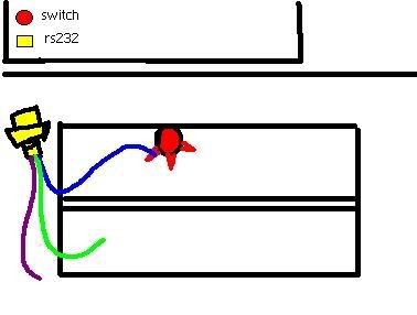
can you see the image above?
that's my problem.
where will i connect those wires??
and what wires will i connect to the switch.
thats it.
if i got that, the the next part is the programming.
ill just listen if some switch says "1" then i'l play a sound.
so how?
4,359
December 21, 2008 04:34 AM
Actually, if 8 bits is enough, you could drive the data bits of a parallel port directly with the switches. Then, the difficulty would be on the software side.
The downside of this approach is that if you ever need to send more data besides these 8 bits (and you will eventually want to), you don't have any data channels left and by that time, you would probably need a separate logic controller anyway.
The downside of this approach is that if you ever need to send more data besides these 8 bits (and you will eventually want to), you don't have any data channels left and by that time, you would probably need a separate logic controller anyway.
Niko Suni
4,359
December 21, 2008 04:37 AM
Quote:
Original post by macmoy
can you see the image above?
that's my problem.
where will i connect those wires??
and what wires will i connect to the switch.
thats it.
if i got that, the the next part is the programming.
ill just listen if some switch says "1" then i'l play a sound.
so how?
You need to make the blue connection with a serial controller (to be exact, one input data pin of the controller per switch), if you are going to use a serial port and/or multiple switches. Generally speaking, it is not so simple as to just solder a pin of the D-sub socket to the switch and hope for the best. This is why the controller chip is necessary.
Niko Suni
This topic is closed to new replies.
Advertisement
Popular Topics


Advertisement
Recommended Tutorials

Advertisement