Welcome to the first part of multiple effect articles about soft shadows. In recent days I've been working on area light support in my own game engine, which is critical for one of the game concepts I'd like to eventually do (if time will allow me to do so). For each area light it is crucial to have proper soft shadows with proper penumbra. For motivation, let's have the following screenshot with 3 area lights with various sizes:
Fig. 01 - PCSS variant that allows for perfectly smooth, large-area light shadows
Let's start the article by comparison of the following 2 screenshots - one with shadows and one without:
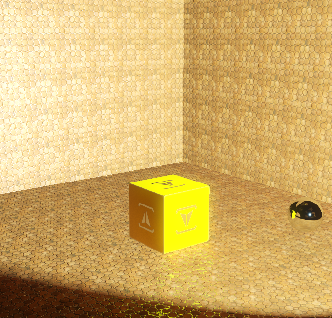
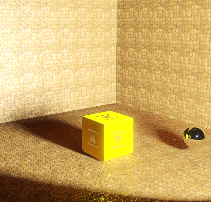
Fig. 02 - Scene from default viewpoint lit with light without any shadows (left) and with shadows (right)
This is the scene we're going to work with, and for the sake of simplicity all of the comparison screenshots will be from this exactly same viewpoint with 2 different scene configurations. Let's start with definition of how shadows are created. Given a scene and light which we're viewing. Shadow umbra will be present at each position where there is no direct visibility between given position and any existing point on the light. Shadow penumbra will be present at each position where there is visibility of any point on the light, yet not all of them. No shadow is everywhere where there is full direct visibility between each point on the light and position.
Most of the games tend to simplify, instead of defining a light as area or volume, it gets defined as infinitely small point, this gives us few advantages:
- For single point it is possible to define visibility in binary way - either in shadow, or not in shadow
- From single point, a projection of the scene can be easily constructed in such way, that definition of shadow becomes trivial (either position is occluded by other objects in scene from lights point of view, or it isn't)
From here, one can follow into the idea of shadow mapping - which is a basic technique for all others used here.
Standard Shadow Mapping
Trivial, yet should be mentioned here.
inline float ShadowMap(Texture2D<float2> shadowMap, SamplerState shadowSamplerState, float3 coord)
{
	return shadowMap.SampleLevel(shadowSamplerState, coord.xy, 0.0f).x < coord.z ? 0.0f : 1.0f;
}
Fig. 03 - code snippet for standard shadow mapping,where depth map (stored 'distance' from lights point of view) is compared against calculated 'distance' between point we're computing right now and given light position. Word 'distance' may either mean actual distance, or more likely just value on z-axis for light point of view basis.
Which is well known to everyone here, giving us basic results, that we all well know, like:
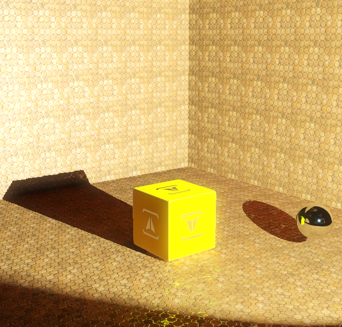
Fig. 04 - Standard Shadow Mapping
This can be simply explained with following image:
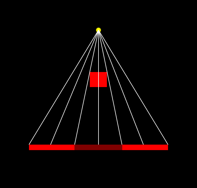
Fig. 05 - Each rendered pixel calculates whether its 'depth' from light point is greater than what is written in 'depth' map from light point (represented as yellow dot), white lines represent computation for each pixel.
Percentage-Close-Filtering (PCF)
To make shadow more visually appealing, adding soft-edge is a must. This is done by simply performing NxN tests with offsets. For the sake of improved visual quality I've used shadow mapping with bilinear filter (which requires resolving 4 samples), along with 5x5 PCF filtering:
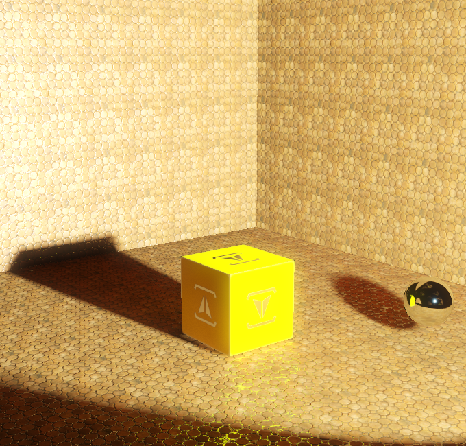
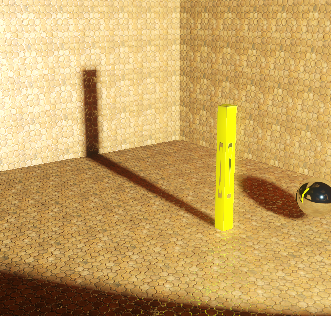
Fig. 06 - Percentage close filtering (PCF) results in nice soft-edged shadows, sadly the shadow is uniformly soft everywhere
Clearly, none of the above techniques does any penumbra/umbra calculation, and therefore they're not really useful for area lights. For the sake of completeness, I'm adding basic PCF source code (for the sake of optimization, feel free to improve for your uses):
inline float ShadowMapPCF(Texture2D<float2> tex, SamplerState state, float3 projCoord, float resolution, float pixelSize, int filterSize)
{
	float shadow = 0.0f;
	float2 grad = frac(projCoord.xy * resolution + 0.5f);

	for (int i = -filterSize; i <= filterSize; i++)
	{
		for (int j = -filterSize; j <= filterSize; j++)
		{
			float4 tmp = tex.Gather(state, projCoord.xy + float2(i, j) * float2(pixelSize, pixelSize));
			tmp.x = tmp.x < projCoord.z ? 0.0f : 1.0f;
			tmp.y = tmp.y < projCoord.z ? 0.0f : 1.0f;
			tmp.z = tmp.z < projCoord.z ? 0.0f : 1.0f;
			tmp.w = tmp.w < projCoord.z ? 0.0f : 1.0f;
			shadow += lerp(lerp(tmp.w, tmp.z, grad.x), lerp(tmp.x, tmp.y, grad.x), grad.y);
		}
	}

	return shadow / (float)((2 * filterSize + 1) * (2 * filterSize + 1));
}
Fig. 07 - PCF filtering source code
Representing this with image:
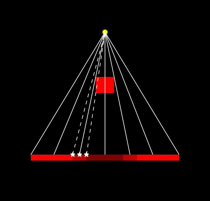
Fig. 08 - Image representing PCF, specifically a pixel with straight line and star in the end also calculates shadow in neighboring pixels (e.g. performing additional samples). The resulting shadow is then weighted sum of the results of all the samples for given pixel.
While the idea is quite basic, it is clear that using larger kernels would end up in slow computation. There are ways how to perform separable filtering of shadow maps using different approach to resolve where the shadow is (Variance Shadow Mapping for example). They do introduce additional problems though.
Percentage-Closer Soft Shadows
To understand problem in both previous techniques let's replace point light with area light in our sketch image.
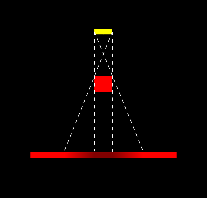
Fig. 09 - Using Area light introduces penumbra and umbra. The size of penumbra is dependent on multiple factors - distance between receiver and light, distance between blocker and light and light size (shape).
To calculate plausible shadows like in the schematic image, we need to calculate distance between receiver and blocker, and distance between receiver and light. PCSS is a 2-pass algorithm that does calculate average blocker distance as the first step - using this value to calculate penumbra size, and then performing some kind of filtering (often PCF, or jittered-PCF for example). In short, PCSS computation will look similar to this:
float ShadowMapPCSS(...)
{
	float averageBlockerDistance = PCSS_BlockerDistance(...);

	// If there isn't any average blocker distance - it means that there is no blocker at all
	if (averageBlockerDistance < 1.0)
	{
		return 1.0f;
	}
	else
	{
		float penumbraSize = estimatePenumbraSize(averageBlockerDistance, ...)
		float shadow = ShadowPCF(..., penumbraSize);
		return shadow;
	}
}
Fig. 10 - Pseudo-code of PCSS shadow mapping
The first problem is to determine correct average blocker calculation - and as we want to limit search size for average blocker, we simply pass in additional parameter that determines search size. Actual average blocker is calculated by searching shadow map with depth value smaller than of receiver. In my case I used the following estimation of blocker distance:
// Input parameters are:
// tex - Input shadow depth map
// state - Sampler state for shadow depth map
// projCoord - holds projection UV coordinates, and depth for receiver (~further compared against shadow depth map)
// searchUV - input size for blocker search
// rotationTrig - input parameter for random rotation of kernel samples
inline float2 PCSS_BlockerDistance(Texture2D<float2> tex, SamplerState state, float3 projCoord, float searchUV, float2 rotationTrig)
{
	// Perform N samples with pre-defined offset and random rotation, scale by input search size
	int blockers = 0;
	float avgBlocker = 0.0f;
	for (int i = 0; i < (int)PCSS_SampleCount; i++)
	{
		// Calculate sample offset (technically anything can be used here - standard NxN kernel, random samples with scale, etc.)
		float2 offset = PCSS_Samples[i] * searchUV;
		offset = PCSS_Rotate(offset, rotationTrig);

		// Compare given sample depth with receiver depth, if it puts receiver into shadow, this sample is a blocker
		float z = tex.SampleLevel(state, projCoord.xy + offset, 0.0f).x;
		if (z < projCoord.z)
		{
			blockers++;
			avgBlockerDistance += z;
		}
	}

	// Calculate average blocker depth
	avgBlocker /= blockers;

	// To solve cases where there are no blockers - we output 2 values - average blocker depth and no. of blockers
	return float2(avgBlocker, (float)blockers);
}
Fig. 11 - Average blocker estimation for PCSS shadow mapping
For penumbra size calculation - first - we assume that blocker and receiver are plannar and parallel. This makes actual penumbra size is then based on similar triangles. Determined as:
penmubraSize = lightSize * (receiverDepth - averageBlockerDepth) / averageBlockerDepth
This size is then used as input kernel size for PCF (or similar) filter. In my case I again used rotated kernel samples. Note.: Depending on the samples positioning one can achieve different area light shapes. The result gives quite correct shadows, with the downside of requiring a lot of processing power to do noise-less shadows (a lot of samples) and large kernel sizes (which also requires large blocker search size). Generally this is very good technique for small to mid-sized area lights, yet large-sized area lights will cause problems.
Fig. 12 - PCSS shadow mapping in practice
As currently the article is quite large and describing 2 other techniques which I allow in my current game engine build (first of them is a variant of PCSS that utilizes mip maps and allows for slightly larger light size without impacting the performance that much, and second of them is sort of back-projection technique), I will leave those two for another article which may eventually come out. Anyways allow me to at least show a short video of the first technique in action:





I'll add some comments while reading, not sure if i'll get it at the end...
receiver->blocker, and receiver->...light position? (seems you forgot to complete the sentence)
I'm confused in general about the term blocker. I assume you next do a search in shadow map to find the closest occluder to the receiving pixel. But at this point i'm confused if blocker means occluder closest to light or closest to receiver. You may clarify this with some explantation.
... ok, i see it's the average of all shadow texels that would shadow the receiver. Finally got it, confusion gone.
Great article, looking towards the next!